Eureka AIR delivers breakthrough ideas for toughest innovation challenges, trusted by R&D personnel around the world.

Bumper rail for vehicle

a technology for bumper rails and vehicles, applied in the direction of bumpers, vehicle components, vehicular safety arrangements, etc., can solve the problems of increasing cost, reducing so as to reduce cost and weight, increase the rigidity of bumper rails, and reduce the effect of weigh

Inactive Publication Date: 2014-10-07
HYUNDAI MOTOR CO LTD
View PDF42 Cites 0 Cited by
  • Summary
  • Abstract
  • Description
  • Claims
  • Application Information

AI Technical Summary

Benefits of technology

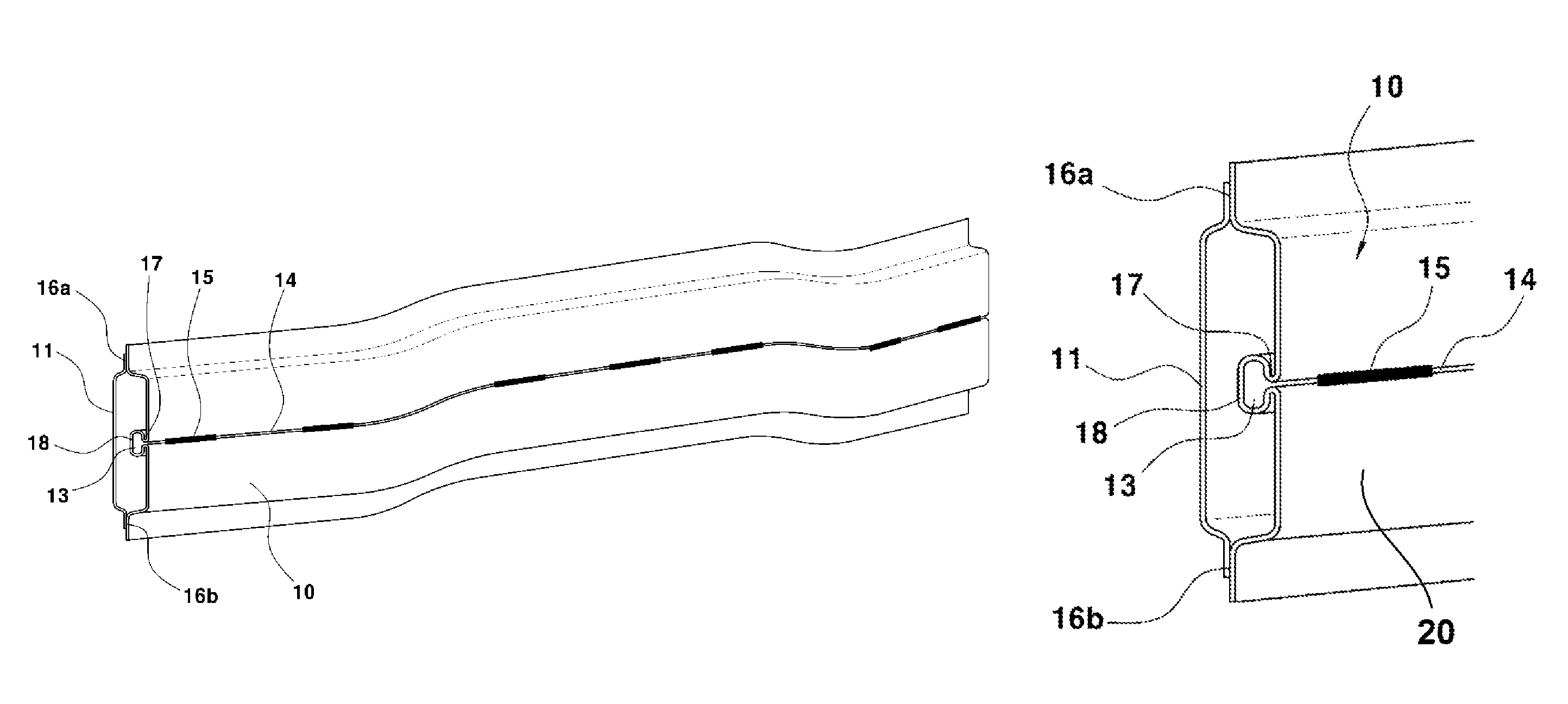
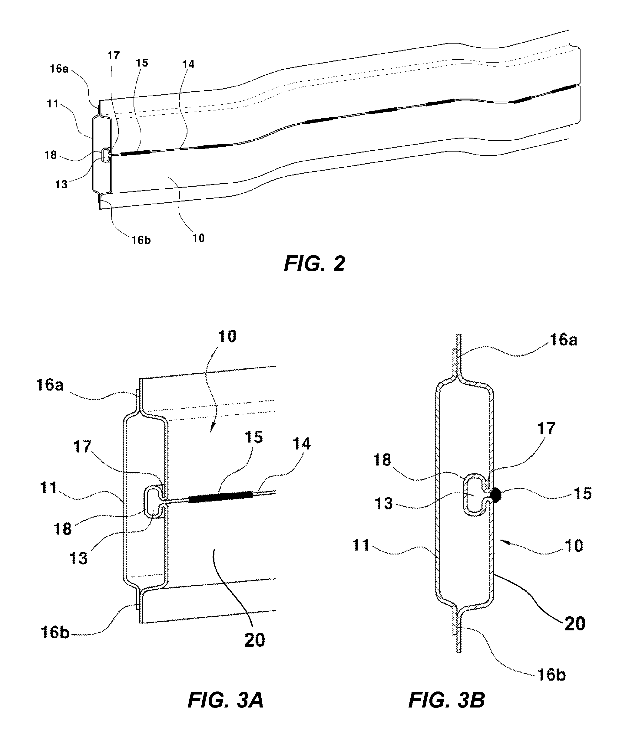
[0021]The present invention provides a bumper rail for a vehicle, which can reduce cost and weight while maintaining the same stiffness as existing pipe welding type, by integrally forming a forming part of a pipe shape at the rear side of the bumper rail and allowing the forming part to show a stiffness equal to that of a typical steel pipe welding type to achieve a new type of bumper rain reinforcement structure that can increase the stiffness of the bumper rail coping with the low-speed crash and the offset crash of vehicles.
[0022]In one aspect, the present invention provides a bumper rail assembled into a bumper of a vehicle, including: a bumper rail disposed at the front side of the bumper rail; a reinforcing member disposed at the rear side of the bumper rail and forming a closed section together with the bumper rail; and a forming part integrally formed at an inner side of the bumper rail and disposed parallel along the longitudinal direction of the bumper rail to increase a stiffness of the bumper rail, the forming part having a pipe shape.
[0026]The forming part having the pipe shape may be disposed in plurality to further increase the stiffness of the bumper rail.

Problems solved by technology

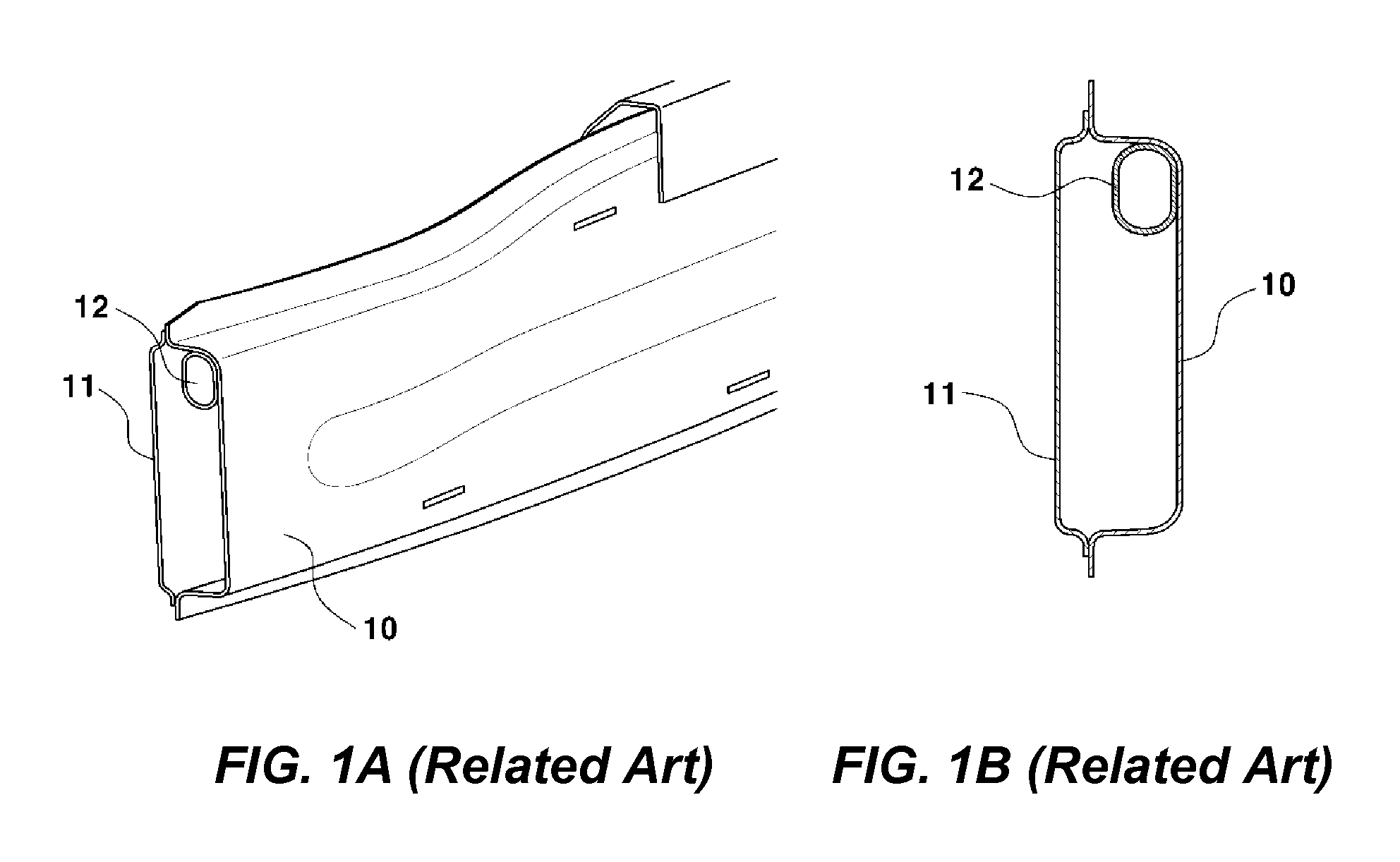
However, a typical bumper rail structure has the following limitations.
First, since the bumper rail has a structure that is welded with an additional pipe, it is disadvantageous in terms of weight and incurs a cost increase.
Second, since the bumper rail and the pipe have to be CO2-welded at about 20 points, the cost increases, and a separate assembly jig is needed.
However, these methods have limitations in that the structure is complicated and the size is disadvantageous in terms of space utilization.
Also, when considering the combination relation with peripheral components, since the whole layout needs to be changed, the efficiency is reduced in terms of actual application.

Method used


Image

  • Bumper rail for vehicle
  • Bumper rail for vehicle
  • Bumper rail for vehicle

Examples


Embodiment Construction

[0033]Reference will now be made in detail to various embodiments of the present invention(s), examples of which are illustrated in the accompanying drawings and described below. While the invention(s) will be described in conjunction with exemplary embodiments, it will be understood that present description is not intended to limit the invention(s) to those exemplary embodiments. On the contrary, the invention(s) is / are intended to cover not only the exemplary embodiments, but also various alternatives, modifications, equivalents and other embodiments, which may be included within the spirit and scope of the invention as defined by the appended claims.

[0034]It is understood that the term “vehicle” or “vehicular” or other similar term as used herein is inclusive of motor vehicles in general such as passenger automobiles including sports utility vehicles (SUV), buses, trucks, various commercial vehicles, watercraft including a variety of boats and ships, aircraft, and the like, and i...


PUM


Abstract

A bumper rail assembled into a bumper of a vehicle includes a bumper rail, a reinforcing member, and a forming part. A bumper rail is disposed at front. The reinforcing member is disposed at the rear side of the bumper rail and forming a closed section together with the bumper rail. The forming part is integrally formed at an inner side of the bumper rail and is disposed parallel along the longitudinal direction of the bumper rail to increase a stiffness of the bumper rail, the forming part having a pipe shape.

Description

CROSS-REFERENCE TO RELATED APPLICATION[0001]The present application claims priority of Korean Patent Application Number 10-2012-0131325 filed Nov. 20, 2012, the entire contents of which application is incorporated herein for all purposes by this reference.BACKGROUND OF INVENTION[0002]1. Field of Invention[0003]The present invention relates to a bumper rail for a vehicle. More particularly, the present invention relates to a bumper rail for a vehicle, which is assembled into the front bumper of the vehicle to increase stiffness.[0004]2. Background Art[0005]Generally, vehicle bumpers are installed both at the front and rear ends of the vehicle to protect a vehicle body, and absorb an impact to protect occupants at the time of vehicle collision.[0006]Bumpers disposed at the front side of the vehicle body have a structure in which a bumper cover, an impact-absorbing foam, and a bumper rail are sequentially arranged, and perform a function of mitigating impact energy from the front impac...

Claims


Application Information

Patent Timeline
Patent Type & Authority Patents(United States)
IPC IPC(8): B60R19/02B60R19/18
CPCB60R19/18B60R2019/1813B60R19/24B60R19/36
Inventor OH, HEE, DAE
Owner HYUNDAI MOTOR CO LTD
Why Eureka
Eureka Blog
Learn More