Outboard engine unit

a technology for engine units and outboard engines, which is applied in the direction of marine propulsion, combustion air/fuel air treatment, and vessel construction, etc., can solve the problems of difficult to sufficiently reduce air intake noise, difficult for the air taken in from the air induction port to circulate to the entire area inside the engine cover, etc., to achieve sufficient ensuring of the increase the total length of the intake channel, and reliably separate from the air

Active Publication Date: 2014-10-07
HONDA MOTOR CO LTD
View PDF8 Cites 8 Cited by
  • Summary
  • Abstract
  • Description
  • Claims
  • Application Information

AI Technical Summary

Benefits of technology

[0013]An object of the present invention is to provide an outboard engine unit capable of cooling the entire area inside the engine cover.
[0014]Another object of the present invention is to provide an outboard engine unit that can sufficiently reduce air intake noise, and that can minimize entry of water into the throttle unit.

Problems solved by technology

In other words, it is difficult for the air taken in from the air induction port to circulate to the entire area inside the engine cover.
However, it is difficult to sufficiently reduce air intake noise using a method that transmits air intake noise laterally.

Method used


Image

  • Outboard engine unit
  • Outboard engine unit
  • Outboard engine unit

Examples


first embodiment

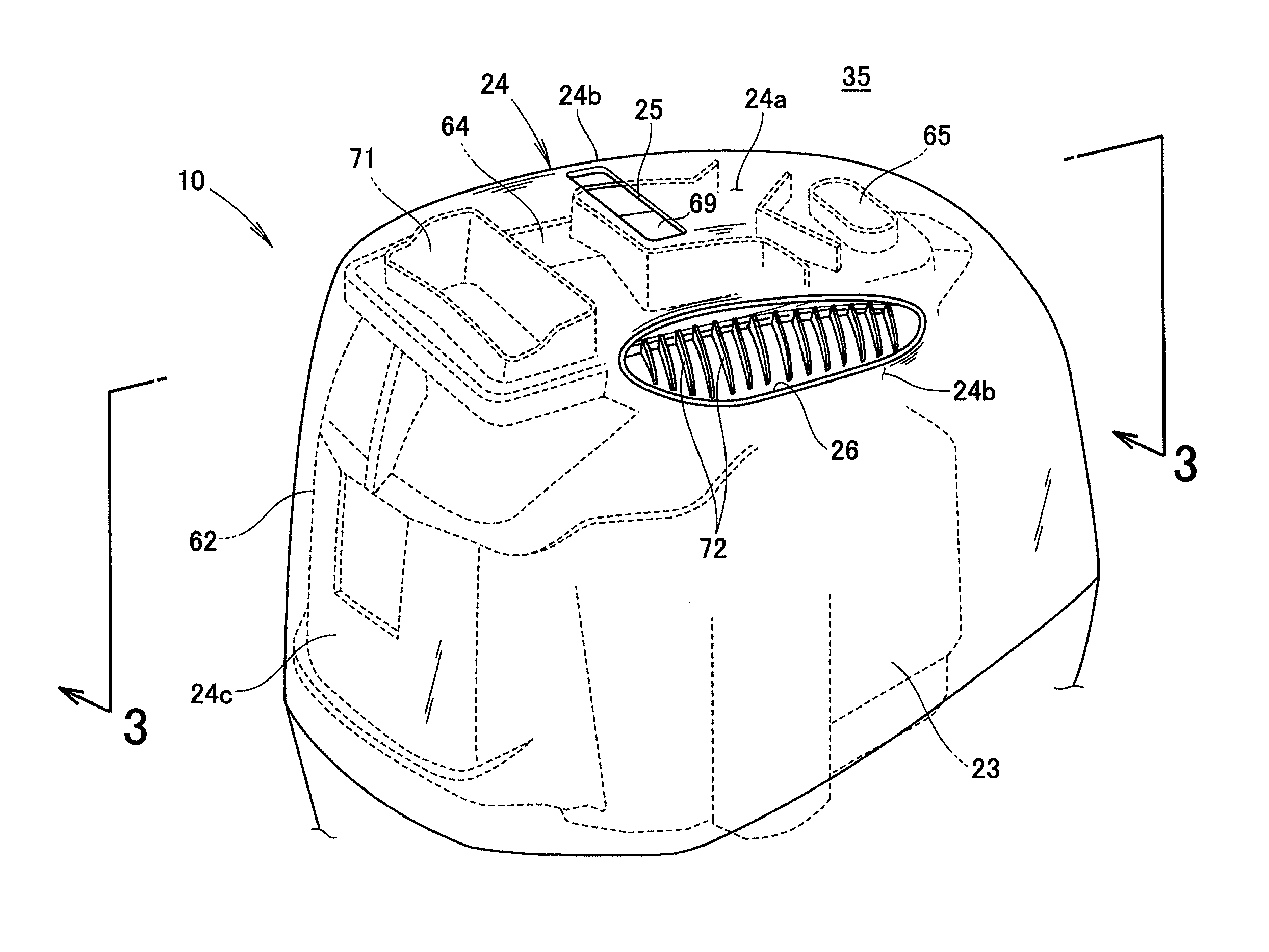
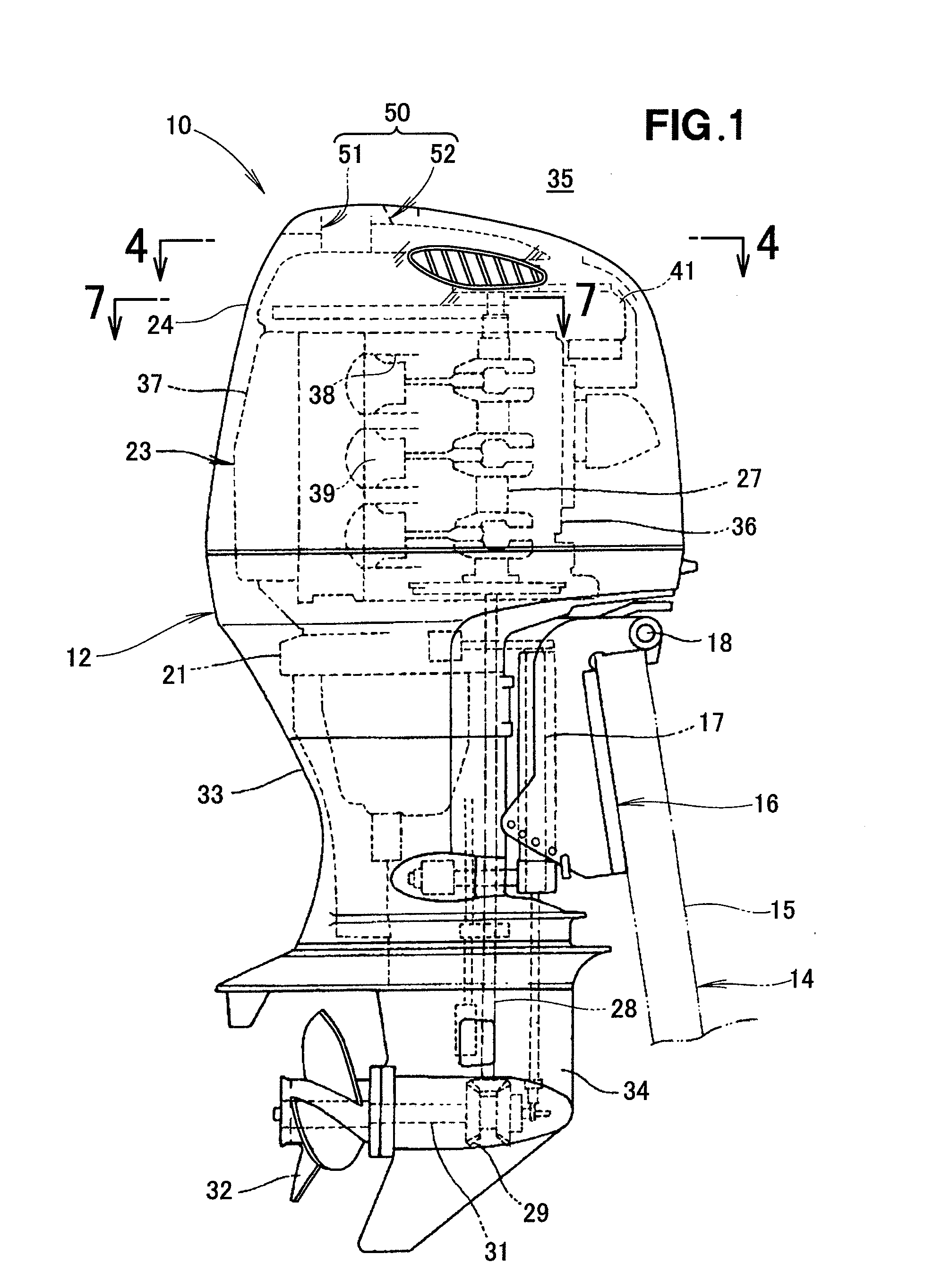
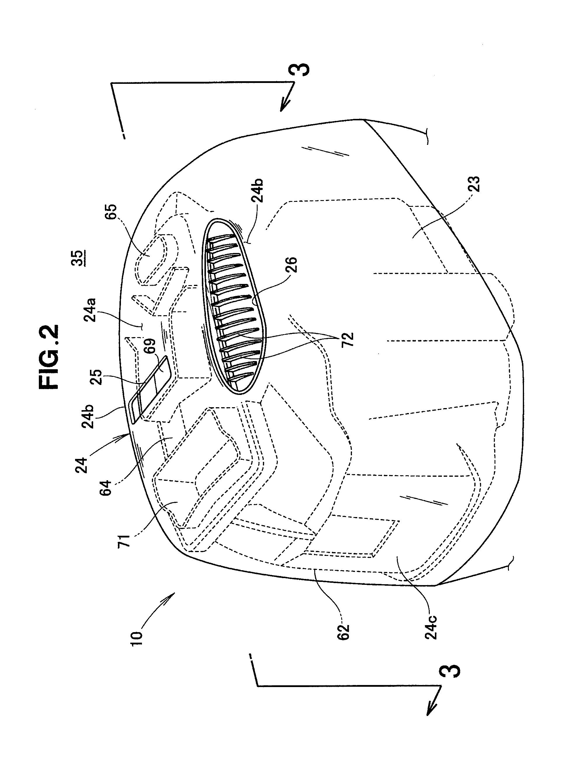
[0078]As shown in FIG. 1, the outboard engine unit 10 of a first embodiment is provided with an outboard engine unit body 12, and mounting means 16 detachable from a hull 14 (specifically, a stern 15), the mounting means being provided to the outboard engine unit body 12. The mounting means 16 is provided with a swivel shaft 17 for allowing the outboard engine unit body 12 to pivot in the lateral direction (horizontal direction), and a tilt shaft 18 for allowing the outboard engine unit body 12 to pivot in the vertical direction.

[0079]The outboard engine unit body 12 is provided with a mounting case 21 provided to the mounting means 16, an engine 23 equipped in the upper part of the mounting case 21, an engine cover 24 for covering the engine 23, a drive shaft 28 coaxially connected to a crankshaft 27 of the engine 23, a gear mechanism 29 to which the rotations of the engine 23 (crankshaft 27) are transmitted via the drive shaft 28, and a propeller 32 to which the rotations of the g...

second embodiment

[0132]The outboard engine unit 210 in the second embodiment will be described using the same reference numerals for the same members in the first embodiment.

[0133]As shown in FIG. 13, the outboard engine unit 210 in the second embodiment is provided with an outboard engine unit body 12, and mounting means 16 detachable from a hull 14 (specifically, a stern 15), the mounting means being provided to the outboard engine unit body 12. The mounting means 16 is provided with a swivel shaft 17 for allowing the outboard engine unit body 12 to pivot in the lateral direction (horizontal direction), and a tilt shaft 18 for allowing the outboard engine unit body 12 to pivot in the vertical direction.

[0134]The outboard engine unit body 12 is provided with a mounting case 21 provided to the mounting means 16, an engine 23 equipped in the upper part of the mounting case 21, an engine cover 24 for covering the engine 23, a drive shaft 28 coaxially connected to a crankshaft 27 of the engine 23, a ge...

third embodiment

[0195]The outboard engine unit 310 in the third embodiment will be described using the same reference numerals for the same members in the first and second embodiments.

[0196]As shown in FIG. 23, the outboard engine unit 310 in the third embodiment is provided with an outboard engine unit body 12, and mounting means 16 detachable from a hull 14 (specifically, a stern 15), the mounting means being provided to the outboard engine unit body 12. The mounting means 16 is provided with a swivel shaft 17 for allowing the outboard engine unit body 12 to pivot in the lateral direction (horizontal direction), and a tilt shaft 18 for allowing the outboard engine unit body 12 to pivot in the vertical direction.

[0197]The outboard engine unit body 12 is provided with a mounting case 21 provided to the mounting means 16, an engine 23 equipped in the upper part of the mounting case 21, an engine cover 24 for covering the engine 23, a drive shaft 28 coaxially connected to a crankshaft 27 of the engin...


PUM


Abstract

An outboard engine unit capable of efficiently cooling the interior of an engine cover is disclosed. The outboard engine unit includes a cooling opening capable of guiding air to an interior from an upper part of the engine cover, a first intake channel having a first outlet open to an upper front end and communicating with the opening, a partition wall disposed so as to be oriented substantially in a perpendicular direction below the first outlet; and a second intake channel extending substantially in the perpendicular direction along a rear wall of the engine cover rearward of the partition wall. The outboard engine unit is configured so that air directed from the cooling opening to the interior of the engine cover is directed to the throttle unit via the second cooling air intake channel.

Description

FIELD OF THE INVENTION[0001]The present invention relates to an outboard engine unit for directing air into a combustion chamber via a throttle unit provided to the upstream side of an engine (combustion chamber) disposed inside an engine cover.BACKGROUND OF THE INVENTION[0002]Among known outboard engine units are those including an air induction port disposed in the upper rear of the engine cover, an electrical box disposed in the upper front inside the engine cover, and an engine air intake port disposed in the vicinity of the electrical box (i.e., the upper front inside the engine cover). An example thereof is disclosed in Japanese Patent No. 4,005,198.[0003]In the outboard engine unit disclosed in the above publication, air (from the exterior) is taken into the engine cover from the air induction port, and the air taken into the engine cover is directed to the electrical box via an upper space inside the engine cover. The air directed to the electrical box cools the electrical c...

Claims


Application Information

Patent Timeline
Patent Type & Authority Patents(United States)
IPC IPC(8): B63H21/36F02B61/04
CPCF02B61/045F02M35/10262F02M35/167
Inventor HARADA, YOSHIHIROKAI, MASASHIISHIZUKA, KUNIHIKO
Owner HONDA MOTOR CO LTD
Why Eureka
Try Eureka