Wind powered generator with adaptable blade angles

a generator and wind power technology, applied in renewable energy generation, sustainable manufacturing/processing, greenhouse gas reduction, etc., can solve the problems of limited wind power gathering area, useless force bending the blade to the direction of the wind,

Inactive Publication Date: 2018-07-26
LU GUIXIAN
View PDF0 Cites 0 Cited by
  • Summary
  • Abstract
  • Description
  • Claims
  • Application Information

AI Technical Summary

Benefits of technology

[0002]The primary object of the present invention is to increase efficiency. Blade angles are changeable. The blades moving against wind are parallel to wind direction so that resistance to rotor rotation is minimized. The blade angles of blades gathering wind power are optimized to maximize efficiency. Usually, the area for gathering wind power is limited. The preset invention helps to maximize the size of the blades to cover more area. The blade covers from the top of the area all the way near the ground. And the shape of the blade is rectangular instead of circular. The other object is to reduce the manufacture cost of wind generator with simple structure. One more object is to gather weak wind power with huge blades.

Problems solved by technology

The other is useless force bending the blade to the direction of wind, which requires to strengthen the blade.
Usually, the area for gathering wind power is limited.

Method used


Image

  • Wind powered generator with adaptable blade angles
  • Wind powered generator with adaptable blade angles
  • Wind powered generator with adaptable blade angles

Examples


Embodiment Construction

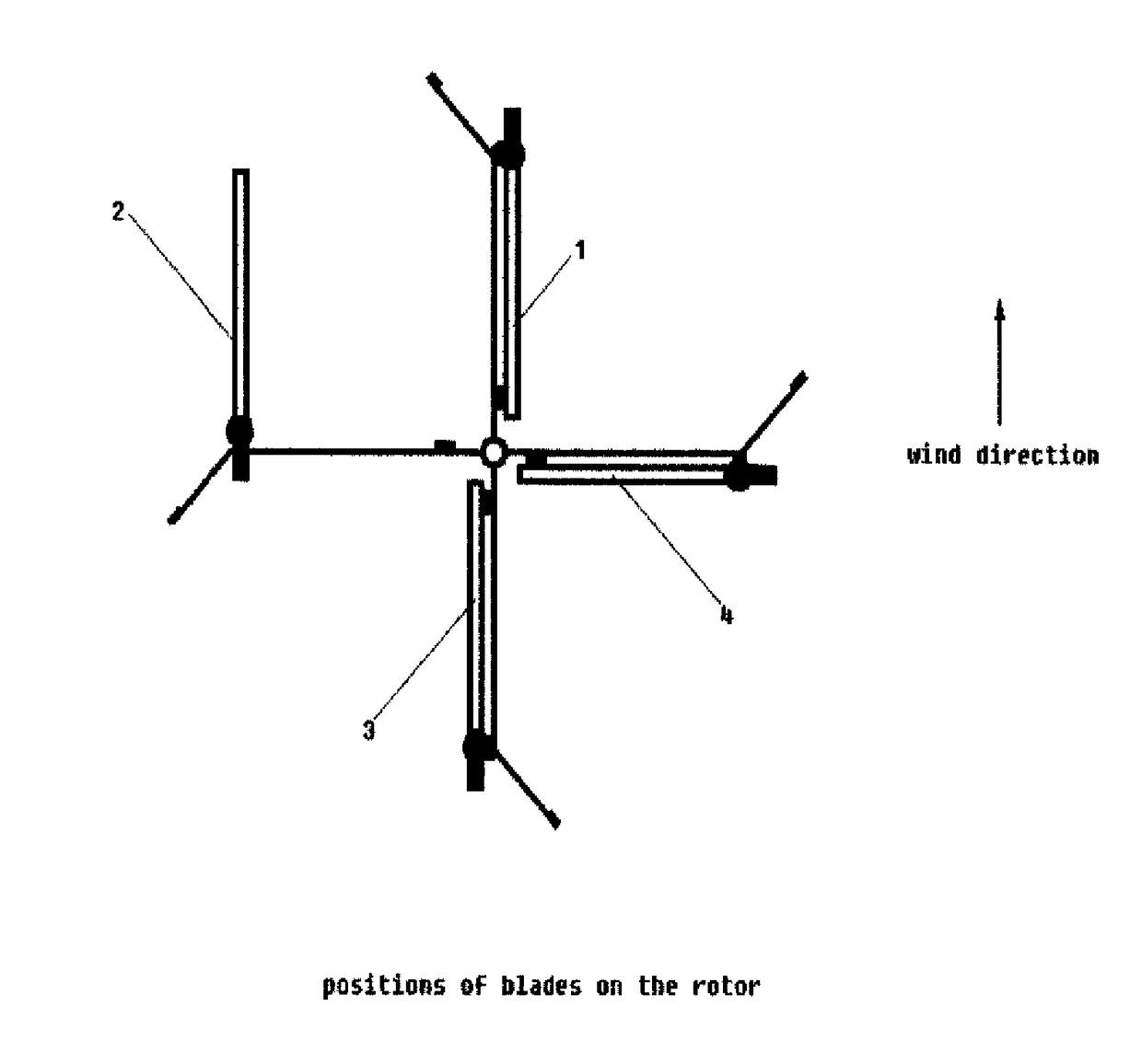
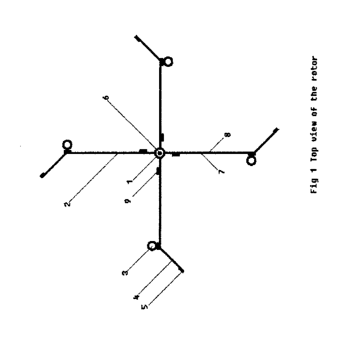
[0006]Let's call the side of rotor where blades gather wind power to rotate the rotor as Wind Power Zone. The right side of rotor in FIG. 3 is Wind Power Zone. Let's call the side of rotor where blades move against wind as Wind Against Zone. The left side of rotor in FIG. 3 is Wind Against Zone. The plane between Wind Power Zone and Wind Against Zone is parallel to wind direction. The rotor center line is in the plane. In this embodiment, the rotor is rotating horizontally and the rotor shaft is vertical. If the rotor shaft is horizontal, it works as well. In that case extra device may be needed to change the direction of rotor shaft when wind changes direction. It can be seen in FIG. 1 that each blade bearing is secured near the end of the rotor arm. The angle between a rotor arm and a blade can vary from zero degree to about 225 degrees. Let's call the angle as Blade Angle. It can be seen in FIG. 3, a blade in position 1 is just before entering Wind Against Zone. When a rotor arm ...


PUM


Abstract

All blades on one side of rotor have good blade angles for gathering wind power. On the other side of rotor, wind turns blades freely so that blades surfaces are parallel to wind direction. There is no need for mechanical means for turning of blades to implements of above operations. This way the wind generator has high efficiency and low manufacture cost.

Description

BACKGROUND OF THE INVENTION[0001]Traditional blades of wind generator look like propellers. The force of wine acts on a blade is equal to two forces. One of the forces is rotating the rotor to generate electricity. The other is useless force bending the blade to the direction of wind, which requires to strengthen the blade.OBJECTS[0002]The primary object of the present invention is to increase efficiency. Blade angles are changeable. The blades moving against wind are parallel to wind direction so that resistance to rotor rotation is minimized. The blade angles of blades gathering wind power are optimized to maximize efficiency. Usually, the area for gathering wind power is limited. The preset invention helps to maximize the size of the blades to cover more area. The blade covers from the top of the area all the way near the ground. And the shape of the blade is rectangular instead of circular. The other object is to reduce the manufacture cost of wind generator with simple structur...

Claims


Application Information

Patent Timeline
Patent Type & Authority Applications(United States)
IPC IPC(8): F03D7/06F03D3/00F03D80/70F03D3/06
CPCF03D7/06F03D3/064F03D80/70F03D3/005F03D3/067F05B2260/79Y02E10/74Y02P70/50
Inventor LU, GUIXIAN
Owner LU GUIXIAN
Why Eureka
Try Eureka