
Stent having expandable elements

Active Publication Date: 2014-10-07
MOB TECH GMBH
View PDF39 Cites 1 Cited by
  • Summary
  • Abstract
  • Description
  • Claims
  • Application Information

AI Technical Summary

Benefits of technology

The patent describes a new design for a stent that can prevent the need for a new stent in most cases. If there is a lot of force applied in the stent's radial direction (a common issue in stent procedures), a part of the stent breaks to release the pressure and allow the vessel to stabilize. Additionally, the stent is made of a material that has a memory effect, which means it can remember its original structure and return to that state if the heat is removed. This improves the stent's ability to support the vessel.

Problems solved by technology

Further radial dilation is not possible because the stent would otherwise deform in an undefined manner and then break.
One of the main problems associated with the use of such stents is the application in young children, in particular in the field of pediatric and neonatal cardiology: In this case, stents having very small starting cross sections must always be used initially due to the small vessel sizes of the young patients.
This replacement requires surgery every time, of course, which is very stressful for the growing patient even if minimally invasive techniques can be used.

Method used


Image

  • Stent having expandable elements
  • Stent having expandable elements
  • Stent having expandable elements

Examples


Embodiment Construction

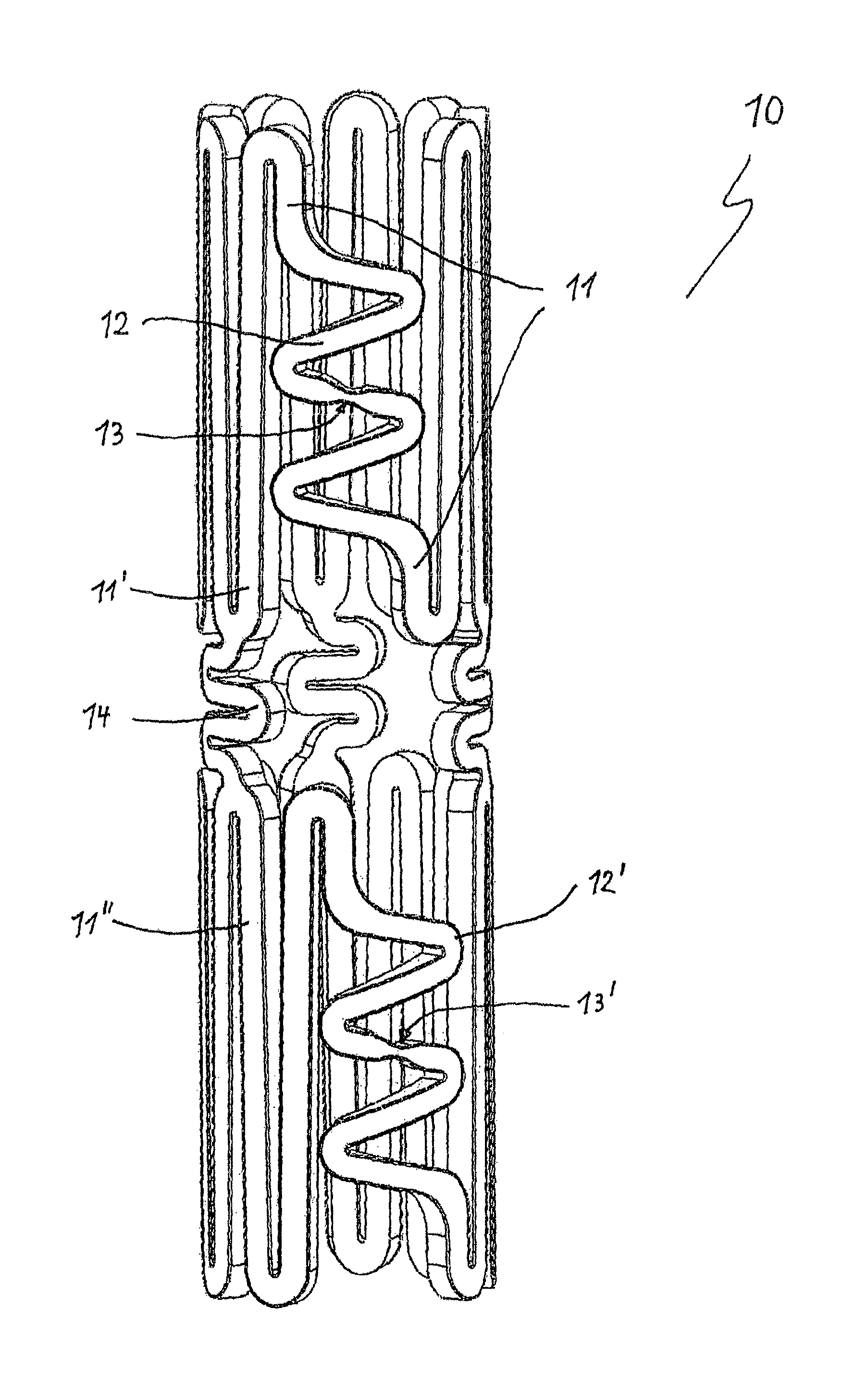
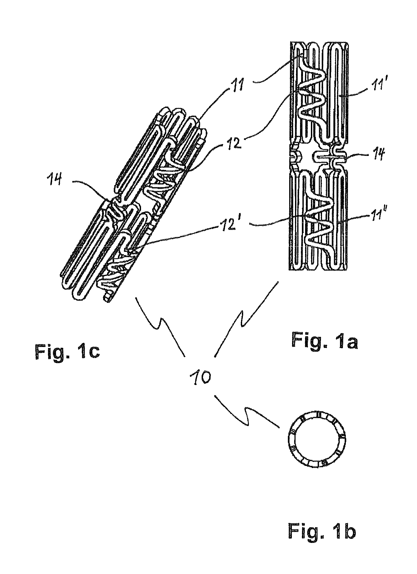
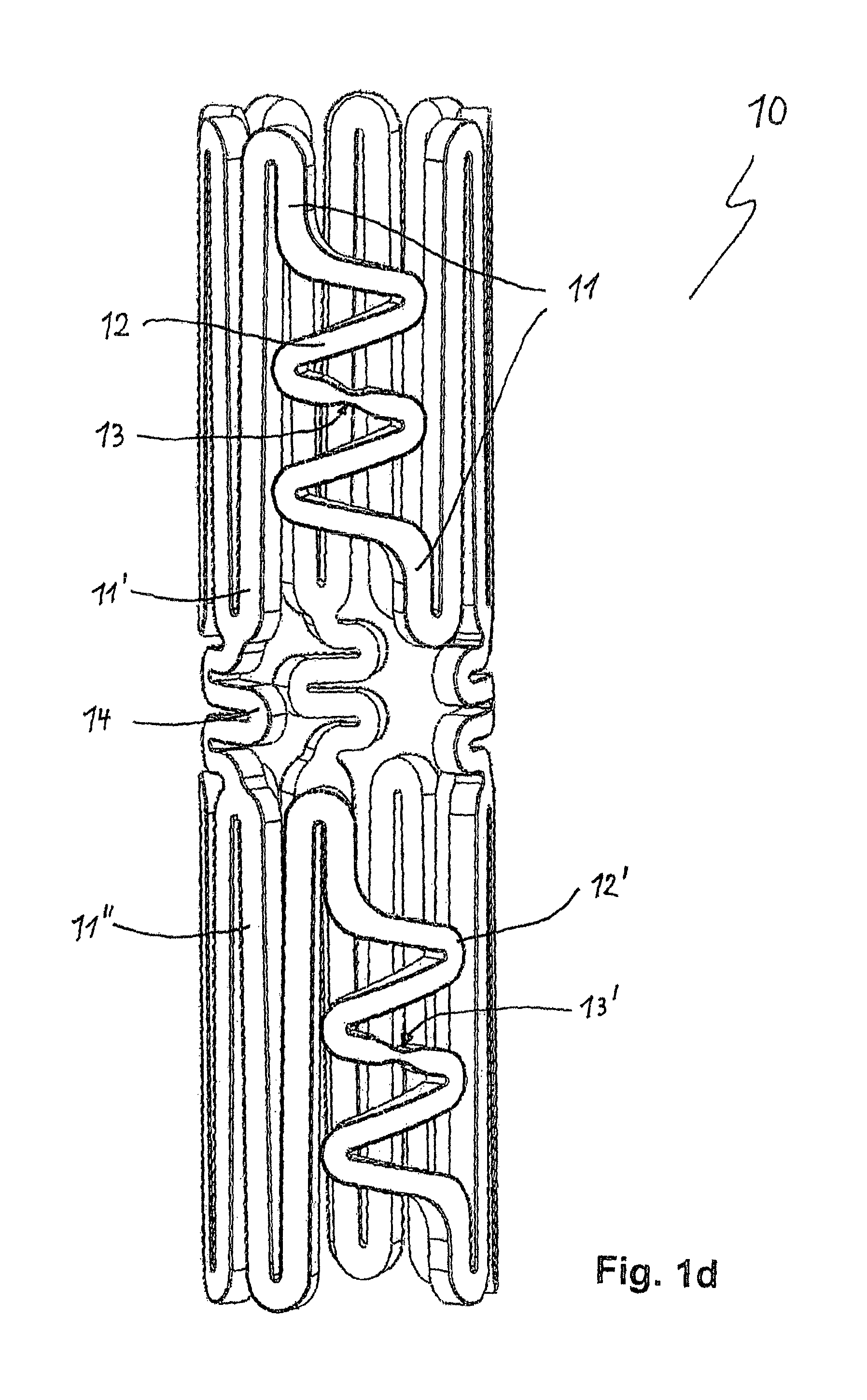
[0039]The embodiments of the medical implant 10; 20 according to the invention, which are depicted schematically in the figures of the drawing, for expanding and supporting a body vessel from the inside thereof (=“stent”), are each designed in the shape of a tube having elongate struts 11,11′,11″; 21,21′,21″ which form a wall of the implant 10; 20 and are plastically deformable at least in sections in such a way that the implant 10; 20 remains permanently expanded in the radial direction transversely to the longitudinal axis of the struts 11,11′,11″; 21,21′,21″ after redilation. To achieve expandability of the implant 10; 20 that is considerably greater than that of known stents, at least one of the struts 11; 21 comprises an expandable element 12,12′; 22; 32a,32b,32c which forms a strut section within said strut 11; 21, in which the expandable element 12,12′; 22; 32a,32b,32c extends partially geometrically transversely to the longitudinal axis of the strut 11; 21 in the contracted ...


PUM


Abstract

A medical implant for the expansion and support of a body vessel is formed as elongate struts in a shape of a tube. The struts are plastically deformable at least in sections so that the implant remains permanently expanded in the radial direction transversely to a longitudinal axis of the struts in the expanded state. A course of the expandable element has a plurality of direction changes with respect to the longitudinal axis. The expandable element has a constriction point in the contracted state designed as an intended breaking point for the expandable element. The constriction point breaks upon application of excessive force applied in the radial direction preventing further expansion of the expandable element.

Description

CROSS-REFERENCE TO RELATED APPLICATION[0001]The invention described and claimed hereinbelow is a National Stage Application of PCT / DE 2006 / 001306, filed Sep. 16, 2009, under 35 USC §371 (the PCT application). The PCT application, whose subject matter is incorporated herein by reference, provides the basis for a claim of priority of the invention under 35 U.S.C. 119(a)-(d).BACKGROUND OF THE INVENTION[0002]The invention relates to a medical implant for the expansion and support of a body vessel from the inside thereof (=“stent”), which can be inserted into the body vessel in a contracted state preferably in a minimally invasive manner, positioned there and transferred into an expanded state, wherein the implant is designed in the shape of a tube having elongate struts which form a wall of the implant, and wherein the struts are plastically deformable at least in sections in such a way that the implant remains permanently expanded in the radial direction transversely to the longitudina...

Claims


Application Information

Patent Timeline
IPC IPC(8): A61F2/06A61F2/91A61F2/915
CPCA61F2/91A61F2/915A61F2250/0082A61F2002/91525A61F2250/001A61F2002/91575A61F2250/0071A61F2002/91583A61F2250/0018A61F2210/0057
Inventor OBRADOVIC, MILISAV
Owner MOB TECH GMBH
Learn More