
Permanent magnet yawing and variable pitch cycloid reduction box for wind power generation

A cycloid deceleration and yaw technology, which is applied in the field of variable pitch gearbox and wind power yaw, can solve the problems of complex structure, high price, long axial dimension, etc., and achieve good machining process performance, uniform manufacturing process, shaft For the effect that the size is short

Active Publication Date: 2015-04-08
NANTONG JIEFU ELECTRICAL CO LTD
View PDF7 Cites 0 Cited by
  • Summary
  • Abstract
  • Description
  • Claims
  • Application Information

AI Technical Summary

Problems solved by technology

[0007] (3) The four-stage planetary deceleration makes the axial dimension very long, the structure is very complicated, the maintenance is very inconvenient, and the price is high
[0008] In addition, there are the following technologies: (1) Tianjin reducer company "used for wind power generation yaw reducer" 200320111939.2 is a cycloid + secondary planetary structure, the disadvantages are: the efficiency is reduced by 2 percentage points, and the high-speed cycloid double fulcrum needle (2) "A Secondary Envelope..." 200920127322.7 of Chongqing University is a cycloid + cycloid structure. The disadvantages are: the efficiency is reduced by 4 percentage points, and the two bearings of the output shaft need 2-3 models larger than normal, the price is very high

Method used


Image

  • Permanent magnet yawing and variable pitch cycloid reduction box for wind power generation

Examples


specific Embodiment approach

[0018] DETAILED DESCRIPTION OF THE PREFERRED EMBODIMENTS The present invention will be described in detail below in conjunction with the accompanying drawings:

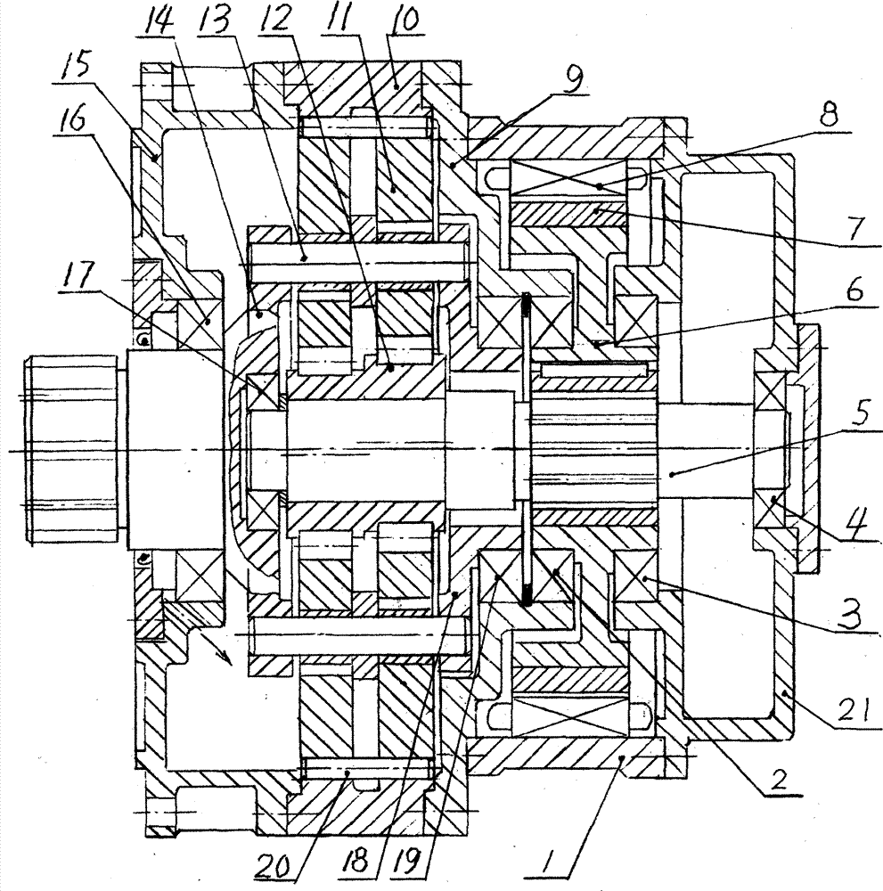
[0019] refer to figure 1 . A permanent magnet yaw-pitch cycloidal reduction box for wind power generation, comprising a permanent magnet motor casing 1, a stator 8, a permanent magnet 7, a hollow rotor 6, and a single-stage cycloidal reduction component, and the front end of the motor casing 1 is sequentially Connect the embedded front end cover 9, the pin gear housing 10 and the machine base 15, and the rear end of the motor housing 1 is connected to the end cover 21, which is characterized in that:

[0020] (A) One side of the hollow rotor 6 is supported by the first bearing 2 in the inner hole of the embedded front end cover 9, and the other side is supported by the second bearing 3 in the inner hole of the end cover 21, and the inner hole of the hollow rotor 6 of the motor is It is slidingly matched with the exte...


PUM


Abstract

The invention relates to the technical field of wind power yawing and variable pitch gearboxes, in particular to a permanent magnet yawing and variable pitch cycloid reduction box for wind power generation. The permanent magnet yawing and variable pitch cycloid reduction box comprises a motor housing, a stator, a permanent magnet, a hollow rotor and a cycloid component. The reduction box is characterized in that two sides of the rotor are respectively supported on a front end cover and an end cover inner hole through bearings, a rotor inner hole is in sliding fit with external splines of an input shaft, and two ends of the input shaft are respectively supported on an output shaft and the end cover inner hole through bearings; and the cycloid component comprises an input shaft upper eccentric bearing, a cycloidal gear, a pin wheel housing, a pin wheel pin and a pin shaft type output mechanism, wherein the output mechanism is composed of the output shaft, a plunger pin, a plunger sleeve and a uniform load ring, the shaft neck of the output shaft is supported on a machine base inner hole through a bearing, and the outer circle of the shaft neck of the uniform load ring is supported on a center hole of the front end cover through a bearing. The permanent magnet yawing and variable pitch cycloid reduction box for the wind power generation has the advantages that load bearing capacity is high, and using is reliable; variable pitch and yawing are the same structure so that the machine model is simplified, and cost is low; the distance in the axial direction is short, and the structure is simple; and the manufacturing cost of the reduction box is about 45%-55% of the manufacturing cost of a reduction box in the prior art.

Description

technical field [0001] The invention relates to the technical field of wind power yaw and pitch variable gearboxes, and relates to a wind power permanent magnet yaw-variable pitch pendulum that can be used as a variable pitch or yaw reducer by changing the frequency, the number of pole pairs and the cycloid reduction ratio. Line reducer. Background technique [0002] (1) Pitch variable gearbox; ① Nanjing High Speed ​​Gear Company "Wind Power Generator Pitch Variable Gearbox" (ZL200410064931); ② Chongqing Gearbox Company "Wind Power Generation Pitch Reduction Gearbox" (200720188097); ③ Tianjin Reducer Company "Used Pitch gear reducer for wind power generation” (200720125070); ④ Hangzhou Qianjin Wind Power Company “wind power pitch reduction gearbox” (200920116858); ⑤ Tailong Group “wind power pitch reduction gear” (200910034380). They are all three-level planetary structures, and their main problems are: [0003] (1) The safety factor of the existing gearbox is low, such as...

Claims


Application Information

Patent Timeline
Patent Type & Authority Patents(China)
IPC IPC(8): H02K7/116H02K5/16F16H1/32
Inventor 吴声震
Owner NANTONG JIEFU ELECTRICAL CO LTD
Learn More