Mounting structure for slot paper in a motor stator

a technology of mounting structure and stator, which is applied in the direction of dynamo-electric machines, electrical apparatus, windings, etc., can solve the problems of reducing the filling ratio of the stator slots, affecting the overall performance of the motor, and reducing the slot volume, so as to maximize the filling ratio of the slots, the structure is simple and reasonable, and the function of precise slot paper positioning is achieved.

Active Publication Date: 2014-10-07
ZHONGSHAN BROAD OCEAN
View PDF9 Cites 6 Cited by
  • Summary
  • Abstract
  • Description
  • Claims
  • Application Information

AI Technical Summary

Benefits of technology

[0007]In view of the above-described problems, it is one objective of the invention to provide a mounting structure for slot paper in a motor stator that has a simple and reasonable structure with precise slot paper positioning function and shall not occupy the space of the stator slots. Thus, the mounting structure maximizes the slot filling ratio of the slots to the largest extent and improves the overall performance of the motor.
[0014]1) the upper end insulator and the lower end insulator each comprises an outer ring and a plurality of tooth block segments extending from the inner wall thereof; the outer ring is arranged on the surface of the stator yoke; the tooth block segments are arranged on the surface of the stator teeth; a lug boss is protruded between two adjacent tooth block segments and from the inner wall of the outer ring; two ends of the slot paper extend out of each stator slot; the paper bottom closely sticks to the bottom wall of each stator slot, and two ends of the paper bottom are locked between the lug boss arranged on the upper end insulator and the lug boss arranged on the lower end insulator; one end of each of the tooth block segments at both sides of the opening of the stator slot is arranged with a clip slot, and the paper front near the opening is embedded in the clip slot; the structure of both the upper end insulator and the lower end insulator for positioning the slot paper is outside each stator slot. Such structure does not occupy the space of the stator slots, thus it maximizes the slot filling ratio of the slots to the largest extent and the overall performance of the motor has been improved;
[0015]2) two ends of the paper bottom of the slot paper are held by two lug bosses, the paper front near the slot opening is embedded in the clip slot to form a triangle structure with two locked points and one supporting point. Consequently, the slot paper can be precisely and securely positioned without any deformation and meanwhile such structure is simple and mounting friendly; and
[0016]3) the upper end insulator and the lower end insulator is each arranged with a convex column, which is sheathed in the positioning hole of the stator core, so that the slot paper can be simply mounted and precisely positioned.

Problems solved by technology

For conventional brushless motors, a plurality of components is protruded from the end insulation portion into the slots to press or clamp the slot paper, which, however, makes the slot volume decreased and reduces the filling ratio of the stator slots, i.e. ratio of space filled by stator windings, thereby affecting the overall performance of the motor.

Method used


Image

  • Mounting structure for slot paper in a motor stator
  • Mounting structure for slot paper in a motor stator
  • Mounting structure for slot paper in a motor stator

Examples


Embodiment Construction

[0024]The invention is explained in further detail below with the reference to the embodiments and attached drawings.

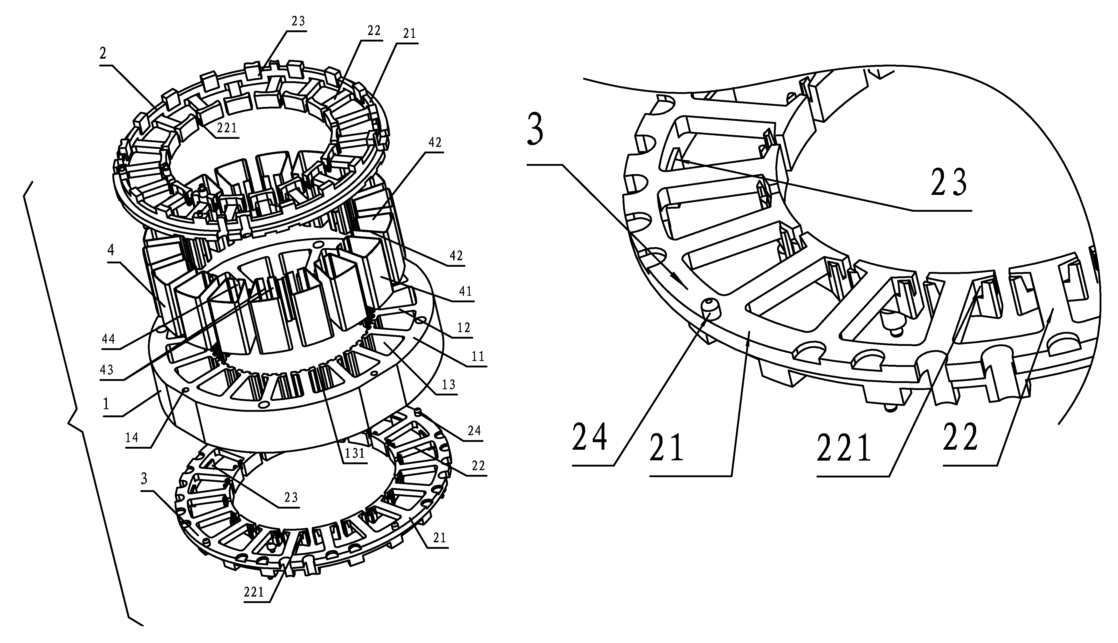
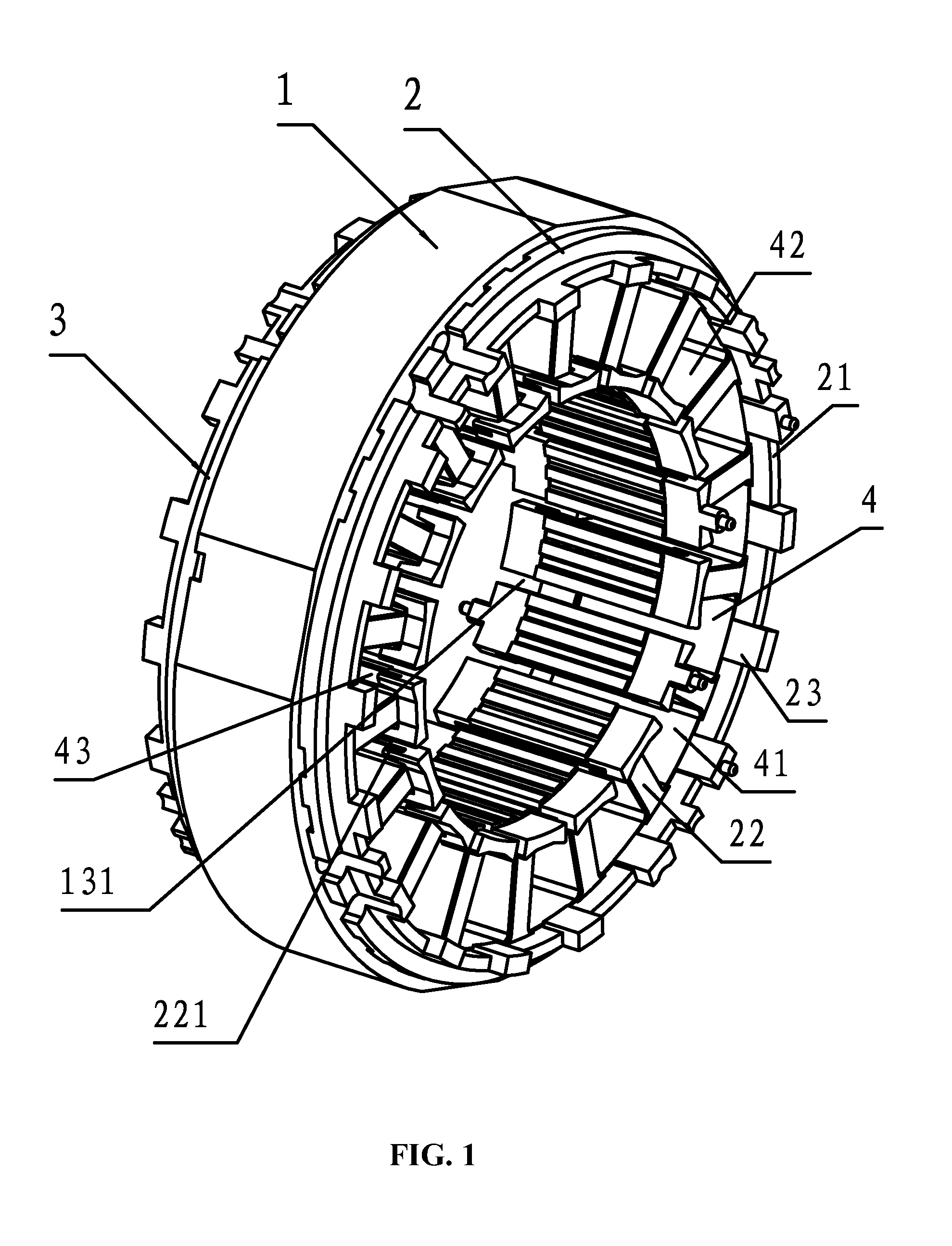
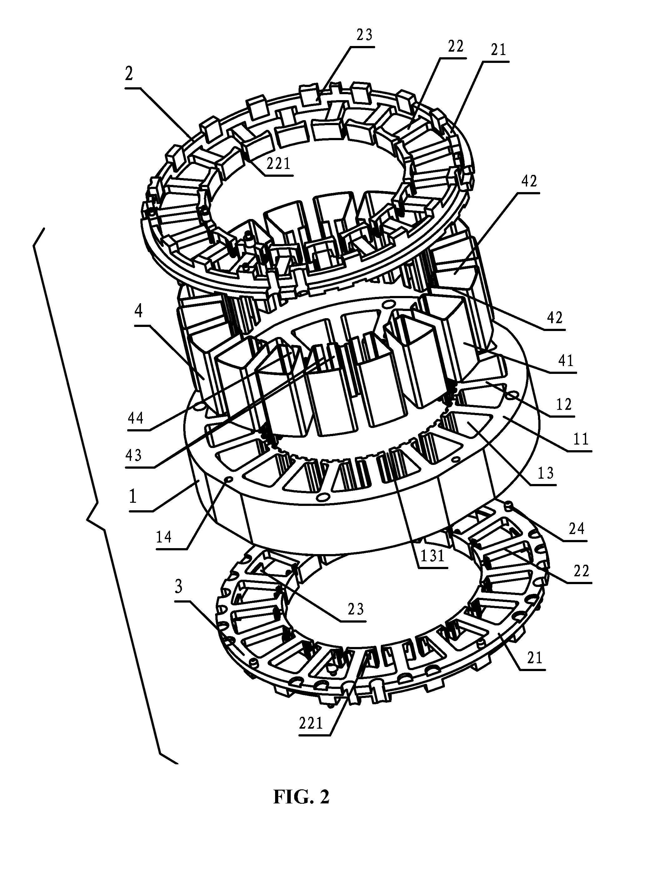
[0025]As shown in FIGS. 1-7, a mounting structure for slot paper in a motor stator, in accordance with the invention, comprises a stator core 1, an upper end insulator 2, a lower end insulator 3, and slot paper 4. The upper end insulator 2 and the lower end insulator 3 are mounted on two end surfaces of the stator core 1, respectively. The stator core 1 comprises a stator yoke 11, stator teeth 12, and stator slots 13 having an opening 131. The slot paper 4 is embedded in the stator slots 13. The slot paper 4 comprises a paper bottom 41, a paper side 42, and a paper front 43. The upper end insulator 2 and the lower end insulator 3 each comprises an outer ring 21 and a plurality of tooth block segments 22 extending from the inner wall thereof. The outer ring 21 is arranged on the surface of the stator yoke 11. The tooth block segments 22 are arranged on the surface of t...


PUM


Abstract

A mounting structure for slot paper in a motor stator. The slot paper is embedded in stator slots and includes a paper bottom, a paper side, and a paper front. A lug boss is protruded between two adjacent tooth block segments and protrudes from the inner wall of an outer ring. Two ends of the slot paper extend out of each stator slot. Two ends of the paper bottom are locked between the lug bosses respectively arranged on the upper end insulator and the lower end insulator. One end of each tooth block segment is provided with a clip slot and the paper front near the opening is embedded therein. The structure is simple, has a precise slot paper positioning function, does not occupy space of the stator slot, maximizes the slot filling ratio of the slots, and thus improves the overall performance of the motor.

Description

CROSS-REFERENCE TO RELATED APPLICATIONS[0001]Pursuant to 35 U.S.C. §119 and the Paris Convention Treaty, this application claims the benefit of Chinese Patent Application No. 201020680566.0 filed Dec. 20, 2010, the contents of which are incorporated herein by reference.BACKGROUND OF THE INVENTION[0002]1. Field of the Invention[0003]The invention relates to a mounting structure for slot paper in a motor stator.[0004]2. Description of the Related Art[0005]A conventional mounting structure for slot paper in a motor stator includes a stator core, an upper end insulator, a lower end insulator, and slot paper, in which the upper end insulator and the lower end insulator are mounted on two end surfaces of the stator core, respectively. The stator core includes a stator yoke, stator teeth, and stator slots. The slot paper is embedded in the slots. The slot paper, the upper end insulator, and the lower end insulator provide insulation for the stator, thereby enabling the coil winding to be i...

Claims


Application Information

Patent Timeline
Patent Type & Authority Patents(United States)
IPC IPC(8): H02K3/34H02K3/52
CPCH02K3/345H02K3/522
Inventor TANG, SONGFA
Owner ZHONGSHAN BROAD OCEAN
Why Eureka
Try Eureka