Joint recognition member

a recognition member and joint technology, applied in the field of joint recognition, can solve the problems of increasing cost and increasing cost, and achieve the effect of reducing manufacturing cost and fast recognition

Inactive Publication Date: 2014-10-14
ROTE MATE IND
View PDF13 Cites 8 Cited by
  • Summary
  • Abstract
  • Description
  • Claims
  • Application Information

AI Technical Summary

Benefits of technology

[0010]Therefore it is a primary object of the present invention to provide a joint recognition member with features of easy assembling, reduced manufacturing cost and fast recognition.
[0012]One end of the joint body is a cylinder and the other end is a polygonal prism. A polygonal hole is set on an opening end of the cylinder and a magnetic part is mounted on an inner end of the polygonal hole. Thus the drive bit is attracted by a magnetic force of the magnetic part for connection and location after the driver bit being mounted into the polygonal hole. The joint recognition member features on that a narrow neck part with a ring groove is disposed on the cylinder, near the polygonal prism. The ring is wrapped around the narrow neck part and is having a protruding ring set on an inner surface thereof for being mounted and moved freely in the ring groove. A curved surface that is tapered from bottom to top is arranged at an inner wall of the protruding ring so as to make the protruding ring mounted into the ring groove quickly and smoothly. Thus the assembling is easy and convenient. Moreover, a barb part is formed on the top of the curved surface and is able to rest against a top surface of the ring groove. Thus the ring is unable to be moved in the opposite direction and released from the narrow neck part after being assembled and located. The connection between the joint body and the ring is secure and tight.

Problems solved by technology

The disadvantage of such design is in that: the sheath needs to cover the whole tool or cylinder so that the material used requires more and the cost is increased.
This is time-consuming and the cost is getting higher.

Method used


Image

  • Joint recognition member
  • Joint recognition member
  • Joint recognition member

Examples


Embodiment Construction

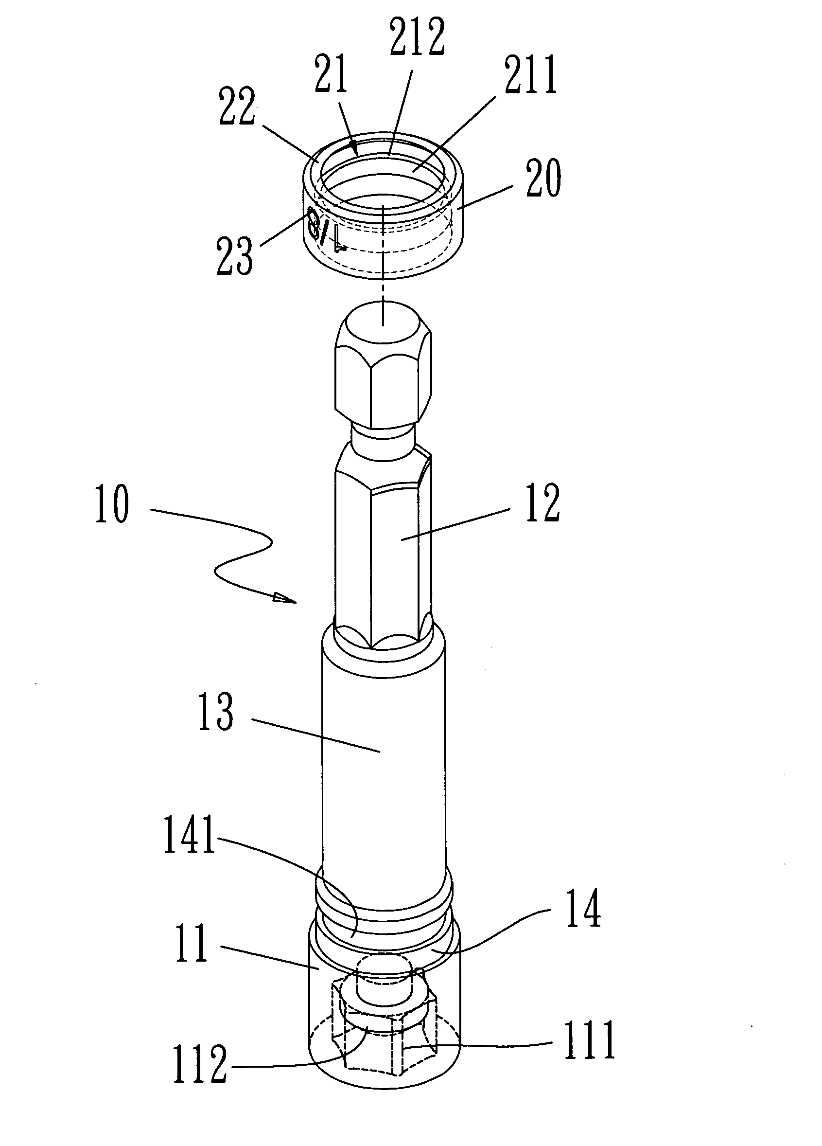
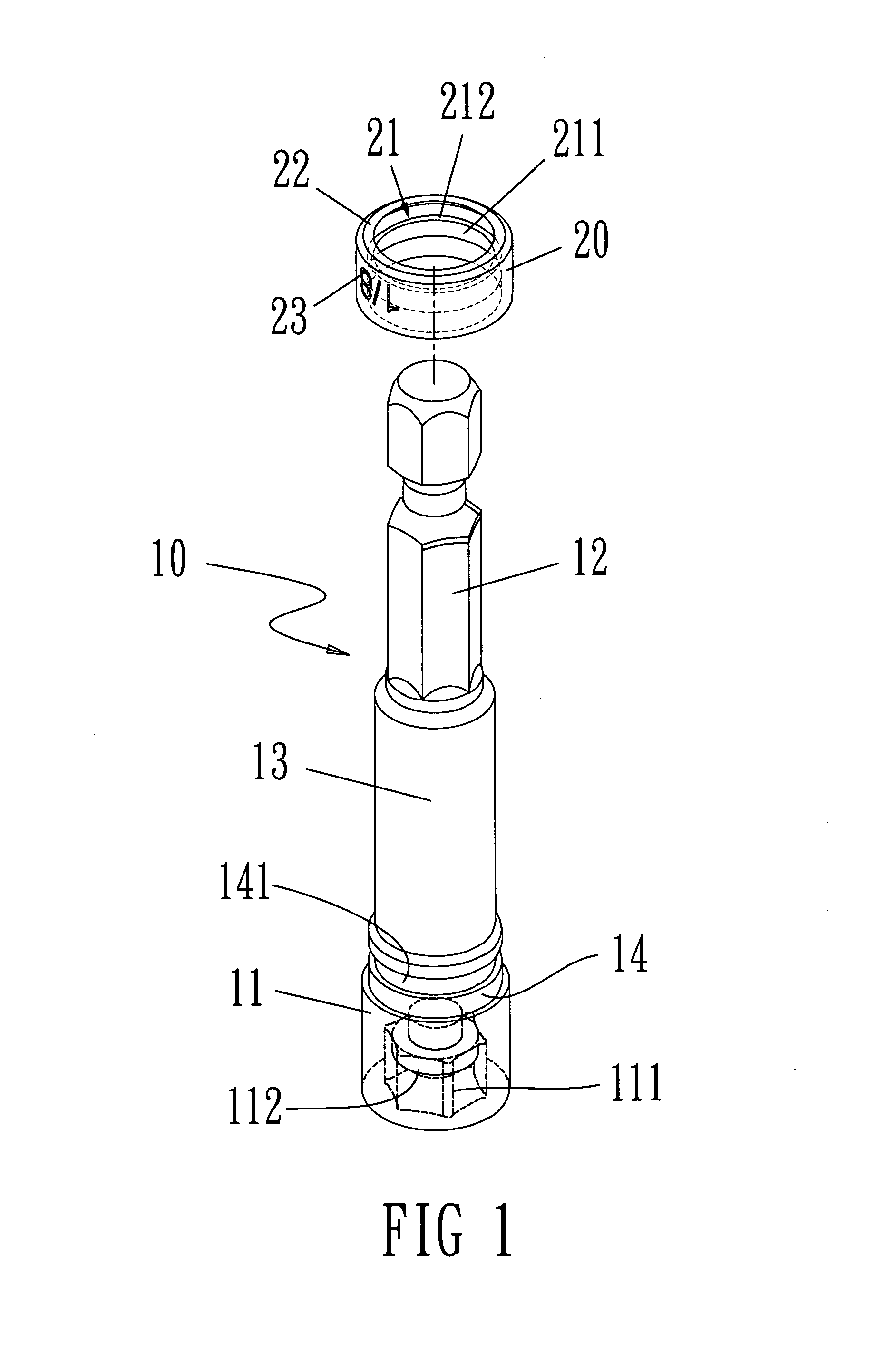
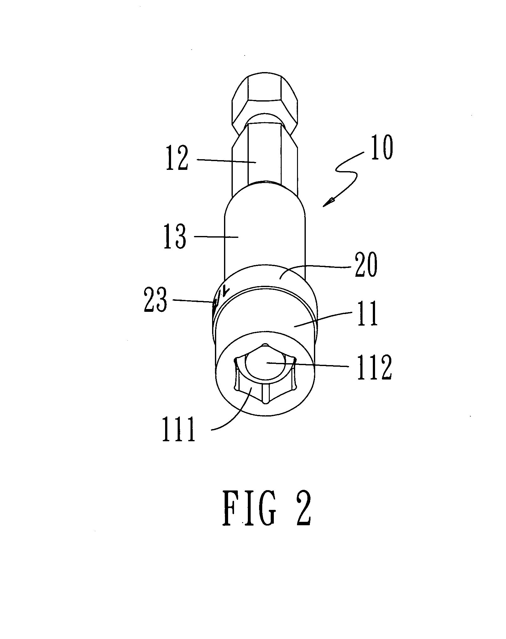
[0030]Refer from FIG. 1 to FIG. 3, an embodiment of a joint recognition member according to the present invention includes a joint body 10 and a ring 20.

[0031]The joint body 10 includes a cylinder 11 on one end and a polygonal prism 12 on the other end thereof. A middle cylinder 13 is connected between the cylinder 11 and the polygonal prism 12. A polygonal hole 111 is set on an opening end of the cylinder 11 and a magnetic part 112 is mounted on an inner end of the polygonal hole 111. Thus a driver bit (not shown in figure) is attracted by a magnetic force of the magnetic part 112 to be connected and located. The outside diameter of the cylinder 11 is larger than the diameter of the polygonal prism 12. Moreover, a narrow neck part 14 with a ring groove 141 is arranged at one end of the cylinder 11 that is near the polygonal prism 12.

[0032]The ring 20 is wrapped around the narrow neck part 14 and is having a protruding ring 21 on an inner surface thereof for being mounted, limited a...


PUM


Abstract

A joint recognition member is revealed. The joint recognition member includes a joint body formed by a cylinder connected with a polygonal prism. A polygonal hole with a magnet part is set on the cylinder so as to attract driver bits by magnetic force. The device features on that: a narrow neck part with a ring groove is arranged at one end of the cylinder near the polygonal prism. The ring is wrapped around the narrow neck part and outside diameter of the ring is no smaller than that of the cylinder. A protruding ring on the ring is mounted and moved freely in the ring groove. An outer surface of the ring is labeled with words such as size. According to the corresponding polygonal hole, the ring has different shapes and sizes in various colors for fast recognition.

Description

BACKGROUND OF THE INVENTION[0001]1. Fields of the invention[0002]The present invention relates to joints assembled with driver bits, especially to joints with rings outside whose size range are recognized by different colors or words on the surface of the ring.[0003]2. Descriptions of Related Art[0004]Generally, a joint is formed by a polygonal prism connected with a cylinder. The polygonal prism is for mounting and connected with driver rods or power tools for rotating. A polygonal hole is arranged axially at a front end of the cylinder and a magnetic body is disposed on an inner end of the polygonal hole so as to replace different types of drivers bits.[0005]Refer to U.S. Pat. No. 7,082,864 “Tool with protective sheath”, and U.S. Pat. No. 5,009,133 “Surface protective fastener tool”, the tools revealed are sleeves connected with drivers or the like such as joints. While applying a sheath to a tool, the sheath covers the whole tool and having at least one end thereof projecting sli...

Claims


Application Information

Patent Timeline
Patent Type & Authority Patents(United States)
IPC IPC(8): B25B23/00B25B13/56B25B15/00B25B23/12G09F3/00
CPCB25B15/001G09F3/00B25B13/56B25B23/12Y10S81/05Y10T403/7039Y10T403/7098Y10T403/592Y10T403/20F16B2200/10
Inventor LAI, YING-TSUNG
Owner ROTE MATE IND
Why Eureka
Try Eureka