Vibration-proof sound box and engagement structure of the same

Active Publication Date: 2014-10-14
LITE ON ELECTRONICS (GUANGZHOU) LTD +1
View PDF19 Cites 2 Cited by
  • Summary
  • Abstract
  • Description
  • Claims
  • Application Information

AI Technical Summary

Benefits of technology

[0006]The object of the present disclosure is to provide a vibration-proof sound box having an engagement structure betw

Problems solved by technology

However coupling by screw consumes labor and time.
However the above technical feature assembles the face cover onto the sound-box main body by cla

Method used


Image

  • Vibration-proof sound box and engagement structure of the same
  • Vibration-proof sound box and engagement structure of the same
  • Vibration-proof sound box and engagement structure of the same

Examples


Example

First Embodiment

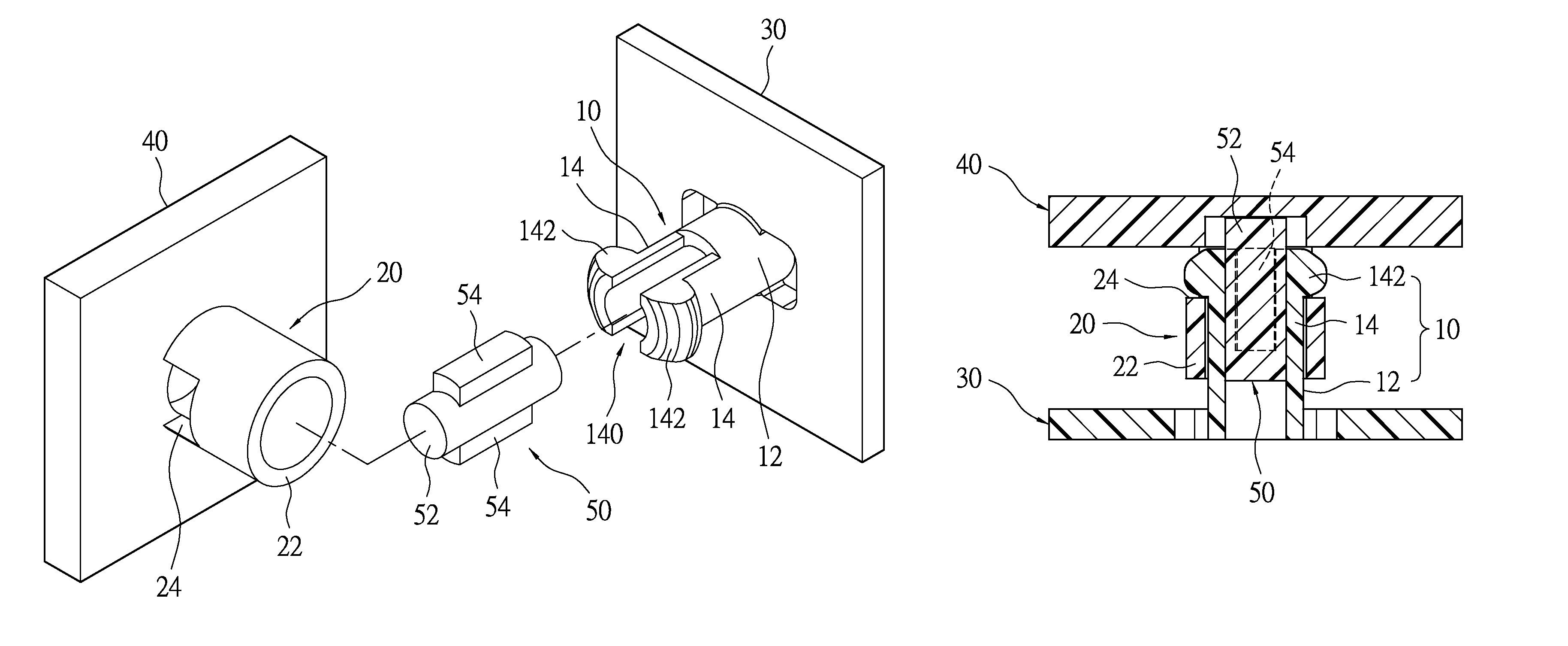
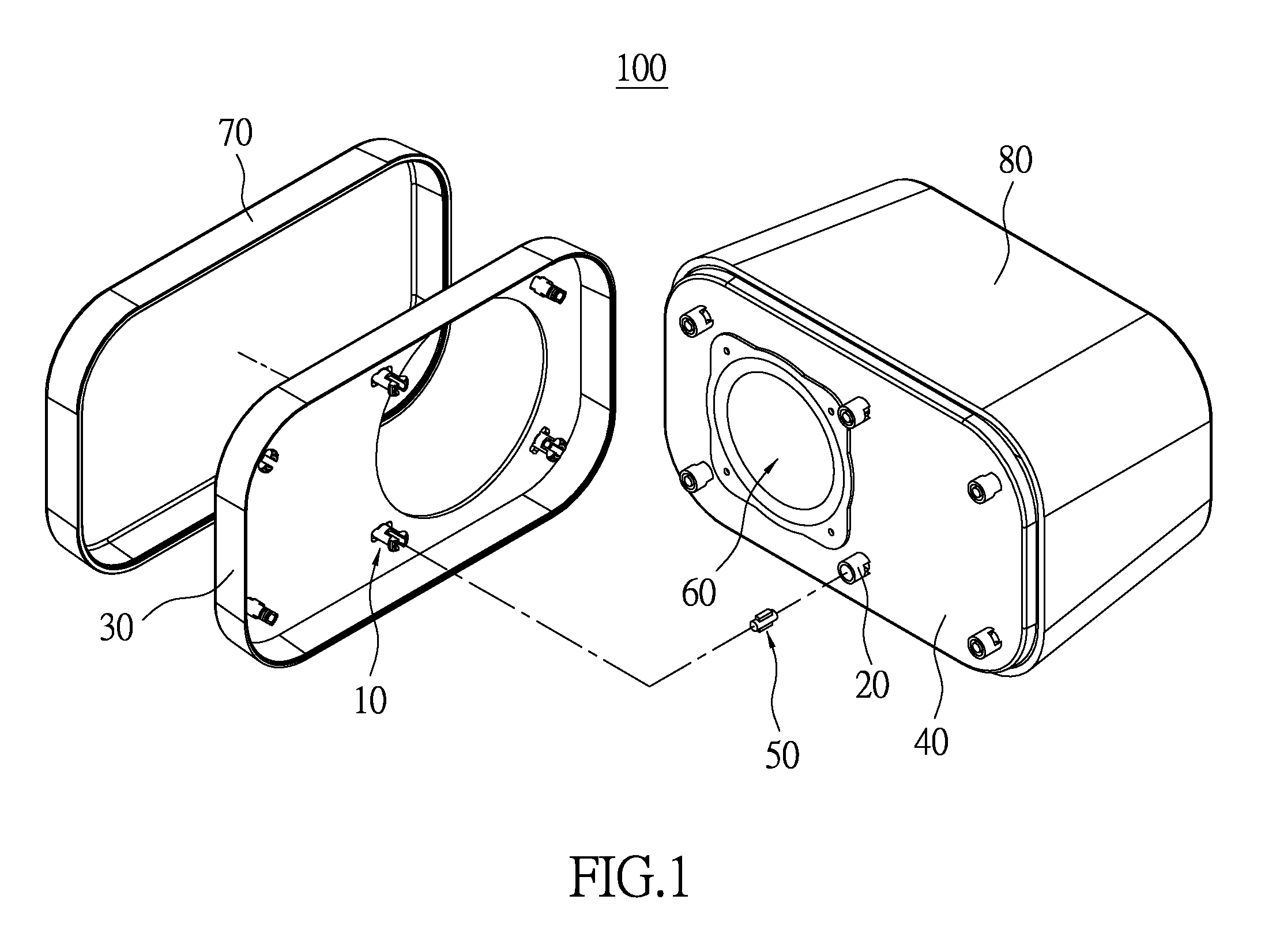
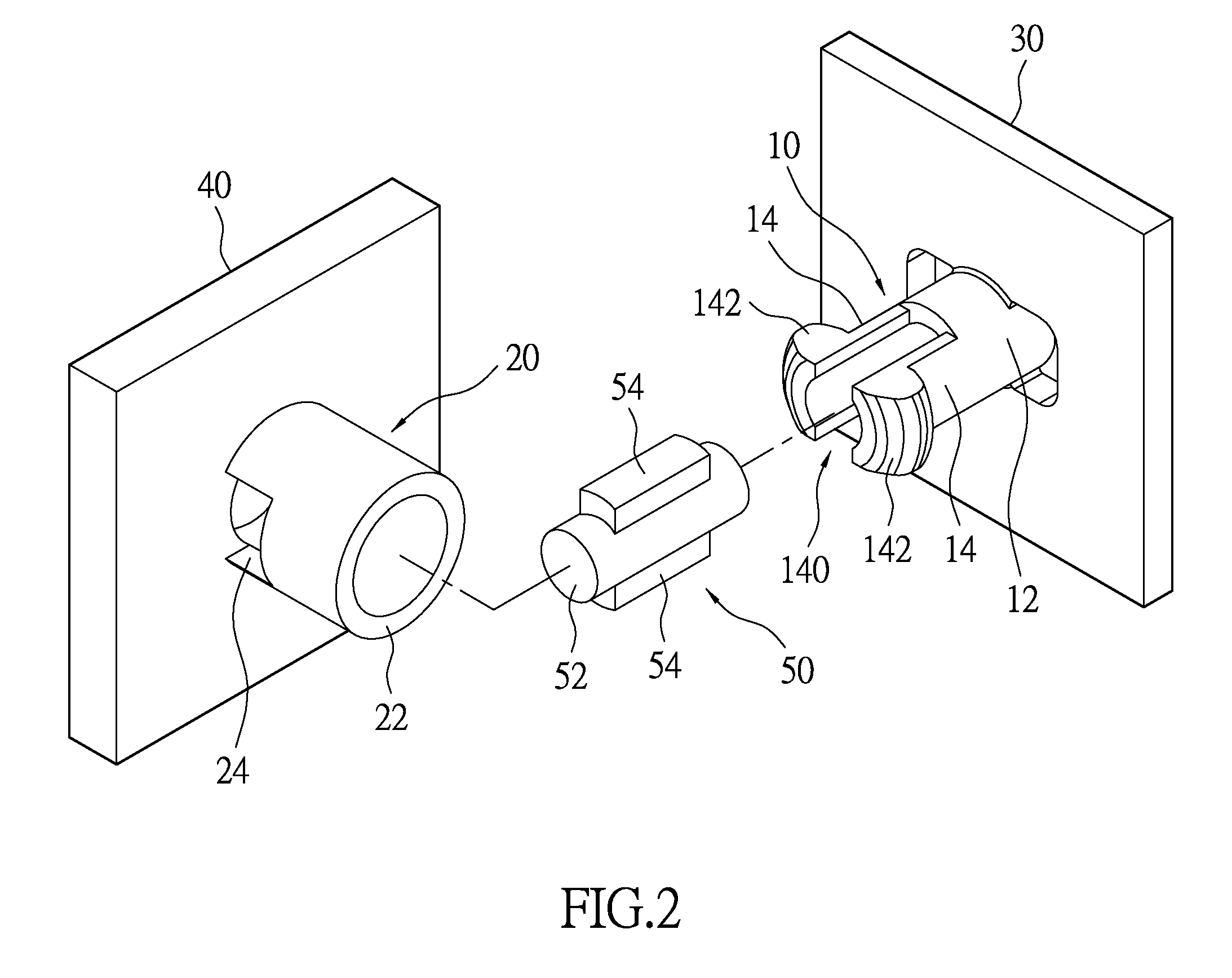
[0021]FIG. 1 and FIG. 2 are respectively a perspective exploded diagram and a partial enlarged diagram of a vibration-proof sound box according to the present disclosure. The vibration-proof sound box 100 of the present disclosure includes a sound box 80, an inner board unit (labeled by 40) fixed to the sound box 80, a speaker 60 installed at the inner board unit, an outer board unit (labeled as 30) disposed at the outer side of the inner board unit, and a mesh 70 covering the outer board unit. The sound box 80 is positioned at one side of the speaker 60. The mesh 70 is positioned at the other side of the speaker 60. The engagement structure is disposed between the inner board unit and the outer board unit to allow the two boards to be assembled quickly without altering their relative positions, stabilize the sound box structure, and provide vibration-proof and retaining functions.

[0022]The engagement structure of the present disclosure not only can be applied on sou...

Example

Second Embodiment

[0031]FIG. 7 and FIG. 8 are perspective exploded diagrams of an engagement structure according to a second embodiment of the present disclosure. The present embodiment demonstrates that the engagement structure of the present disclosure can be independently disposed between any two boards. The clasp 10′ of the present embodiment is locked onto the first board unit 30′ by a screw S1. The screw S1 locks the clasp 10′ perpendicular to the first board unit 30′ along the axial direction of the clasp 10′.

[0032]In the present embodiment, the clasp 10′ has a locking portion 16, and a pair of fixture portions 162 formed at the periphery of the locking portion 16 and extending to the base portion 12. The locking portion 16 is formed with a screw hole 160. The first board unit 30′ has a sleeve portion 34 for accommodating the locking portion 16. The sleeve portion 34 is formed with a pair of fixture grooves 342, and a screw hole 340. The fixture grooves 342 correspond to the f...


PUM


Abstract

A vibration-proof sound box includes a sound box, a first board unit, a speaker, a second board unit, and an engagement structure having a clasp, a holder and a vibration-absorption unit. The clasp has a base portion connected to the first board unit, two clasping arms extending from the base portion, and a clasping space formed between the clasping arms. The free end of each of the clasping arms is formed with a protruding clasping piece. The holder has an accommodating portion connected to the second board unit, and two clasping holes passing through the accommodating portion. The two clasping pieces respectively engage the two clasping holes. The vibration-absorption unit has a main body snugly disposed in the clasping space, and two extension portions extending from the main body. The two extension portions abut the inner wall of the holder.

Description

BACKGROUND OF THE INVENTION[0001]1. Field of the Invention[0002]The present disclosure relates to a vibration-proof sound box and an engagement structure of the same; in particular, to a vibration-proof sound box for speakers and an engagement structure for engaging two boards of the sound box.[0003]2. Description of Related Art[0004]Conventional coupling methods for two boards employ screws for fixtures. However coupling by screw consumes labor and time. Additionally, specific factors for coupling between two boards need to be considered in particular fields, e.g. the speaker quality when applied on a speaker.[0005]The Screw-free Speaker Device according to TW Patent M272341 provides a speaker device which can be assembled without screws. However the above technical feature assembles the face cover onto the sound-box main body by clasping and is unable to avoid transmitting vibration from the speaker to the face cover. The vibration can cause noise and affect the sound quality.SUMM...

Claims


Application Information

Patent Timeline
IPC IPC(8): A47B81/06F16F15/04F16F15/08A47B81/00F16F15/00F16F15/02G10K11/00
CPCG10K11/002H04R1/02H04R1/2869
Inventor LIAO, JUI-CHI
Owner LITE ON ELECTRONICS (GUANGZHOU) LTD
Why Eureka
Try Eureka