
Image capturing apparatus

a technology of image capturing and image, applied in the direction of picture signal generators, solid-state device signal generators, television systems, etc., can solve the problems of cumbersome plurality of shooting operations, limited image, information restriction, etc., and achieve the effect of improving the alignment accuracy between images

Active Publication Date: 2014-10-14
CANON KK
View PDF12 Cites 0 Cited by
  • Summary
  • Abstract
  • Description
  • Claims
  • Application Information

AI Technical Summary

Benefits of technology

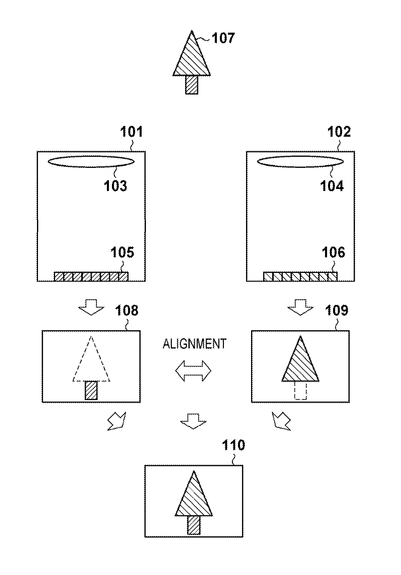
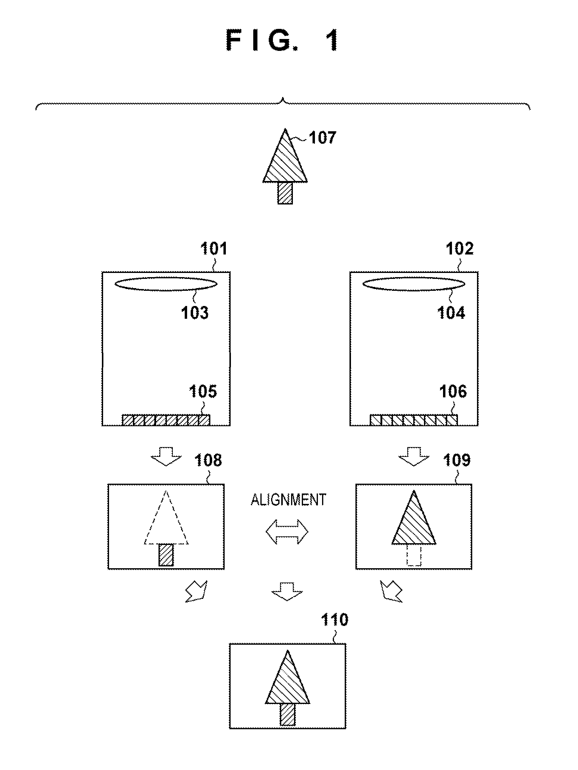
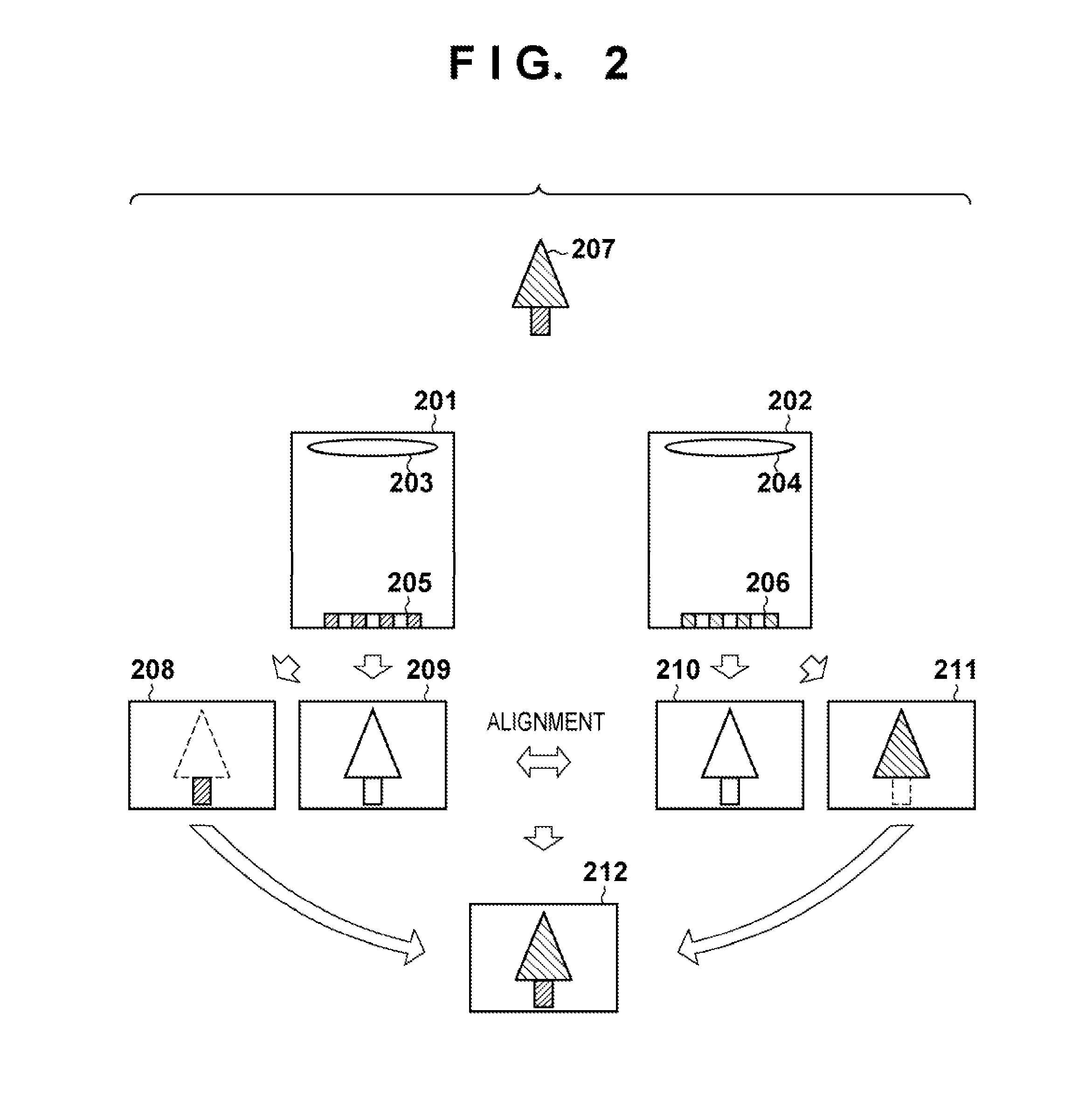
[0012]According to the aspect, the alignment accuracy between images can be improved when generating image data of a multi-channel image.

Problems solved by technology

Color information for an obtained image is limited to these three colors, and even tone information is restricted to a range that is defined by the sensitivity characteristic of the capturing device.
However, the above techniques require a plurality of times of shooting operations cumbersomely, and cannot cope with a moving object.
However, a plurality of images to be aligned are captured by cameras different in color or sensitivity characteristic, so high alignment accuracy cannot be obtained.

Method used


Image

  • Image capturing apparatus
  • Image capturing apparatus
  • Image capturing apparatus

Examples


first embodiment

[0040]An example of capturing a multi-channel image will be explained.

[0041][Arrangement of Image Capturing Apparatus]

[0042]The outer appearance of an image capturing apparatus according to the embodiment will be described with reference to the schematic views of FIGS. 3A and 3B. FIG. 3A shows the front surface (object side) of a camera body 301, and FIG. 3B shows the rear surface of the camera body 301.

[0043]The front surface of the camera body 301 includes a plurality of cameras 305 to 313 (to be referred to as channel cameras) which are arranged in a matrix and correspond to respective channels. The top and rear surfaces of the camera 301 include a shutter button 302, a monitor 303, and an operation unit 304 including buttons and a dial for performing various operations. The user operates the operation unit 304 in accordance with a user interface (UI) displayed on the monitor 303 to set shooting conditions and the like, and presses the shutter button 302 to capture an image. The ...

second embodiment

[0122]An image capturing apparatus according to the second embodiment of the present invention will be described. In the second embodiment, the same reference numerals as those in the first embodiment denote the same parts, and a detailed description thereof will not be repeated.

[0123]The second embodiment will describe an example of acquiring images to undergo high dynamic range composition using a multi-eye camera. The second embodiment is different from the first embodiment in the arrangement of a filter 607 of each of capturing units 401 to 409. The arrangement of the filter 607 according to the second embodiment will be described with reference to FIG. 12.

[0124]Similar to the first embodiment, a Y cell is a luminance capturing filter, and is implemented by arranging a transparent filter or no filter. The Y cells have common characteristics in the capturing units 401 to 409. A combination of the Y cell and capturing element corresponds to the “common element”.

[0125]Rn is a color...

embodiment

Modification of Embodiment

[0133]In the above example, one capturing unit includes one type of common element and three types of specific elements. However, the respective color components may be shot using different capturing units. The embodiment is not limited by the number of types of specific elements.

[0134]In the above description, the alignment pixel represents luminance information. However, the alignment pixel may represent arbitrary color information. The embodiment is not limited by the arrangement and characteristics of the alignment pixel.


PUM


Abstract

Capturing units acquire, from an object, image data having characteristics different from each other. An image generator calculates a deviation amount indicating the position deviation between images represented by the image data acquired by the capturing units, and generates image data of a multi-channel image in which the position deviation between the images represented by the image data acquired by the capturing units has been corrected using the deviation amount. Each of the capturing units comprises capturing elements having capturing characteristics specific to the capturing unit, and capturing elements having capturing characteristics common to a plurality of capturing units. The image generator calculates the deviation amount from image data acquired by the capturing elements having the common capturing characteristics.

Description

BACKGROUND OF THE INVENTION[0001]1. Field of the Invention[0002]The present invention relates to an image capturing apparatus and, more particularly, to an image capturing apparatus which generates image data of a multi-channel image.[0003]2. Description of the Related Art[0004]A color image capturing apparatus such as a digital camera forms an object image via an imaging optical system on a capturing device having color filters arranged periodically, and generates digital image data by photoelectric conversion and analog-to-digital (AD) conversion. In general, color filters for three, R, G, and B colors are used. The sensitivity characteristic of the capturing device is uniform for all pixels. Color information for an obtained image is limited to these three colors, and even tone information is restricted to a range that is defined by the sensitivity characteristic of the capturing device.[0005]When obtaining an image whose color information and tone information are limited, the us...

Claims


Application Information

Patent Timeline
Patent Type & Authority Patents(United States)
IPC IPC(8): H04N5/217H04N5/225H04N5/232H04N5/355H04N9/04
CPCH04N5/2258H04N5/35563H04N9/045H04N5/23232H04N23/45H04N23/951H04N23/631H04N25/585H04N25/135H04N23/843
Inventor KOIZUMI, TATSURO
Owner CANON KK
Learn More