Binocular system

a binocular system and binocular lens technology, applied in the field of binocular lens systems, can solve the problems of putting unnecessary strain on the user, not being desirable, and more visible wearers

Inactive Publication Date: 2014-10-21
N VISION OPTICS
View PDF9 Cites 9 Cited by
  • Summary
  • Abstract
  • Description
  • Claims
  • Application Information

AI Technical Summary

Problems solved by technology

This makes the wearer more visible, which may not be desirable in certain situations (e.g., in military situations).
Additionally, such a configuration may make it difficult to move in some situations and may put unnecessary strain on a user when the components are in the flipped (unused or stowed) position, making the user physically uncomfortable.
However, this does not address the problem of the devices being significantly above the user's head when flipped vertically in the unused (stowed) position.
In addition, heavier components may be desirable for strength, reliability, etc., but not necessarily for improving optical properties.
However, relatively heavy components not only increase a user's physical discomfort when placed in a vertical (raised) position when not used, but may also be uncomfortable in the deployed position due to the weight and the position in front of the head that stresses the user's neck.

Method used


Image

  • Binocular system
  • Binocular system
  • Binocular system

Examples


Embodiment Construction

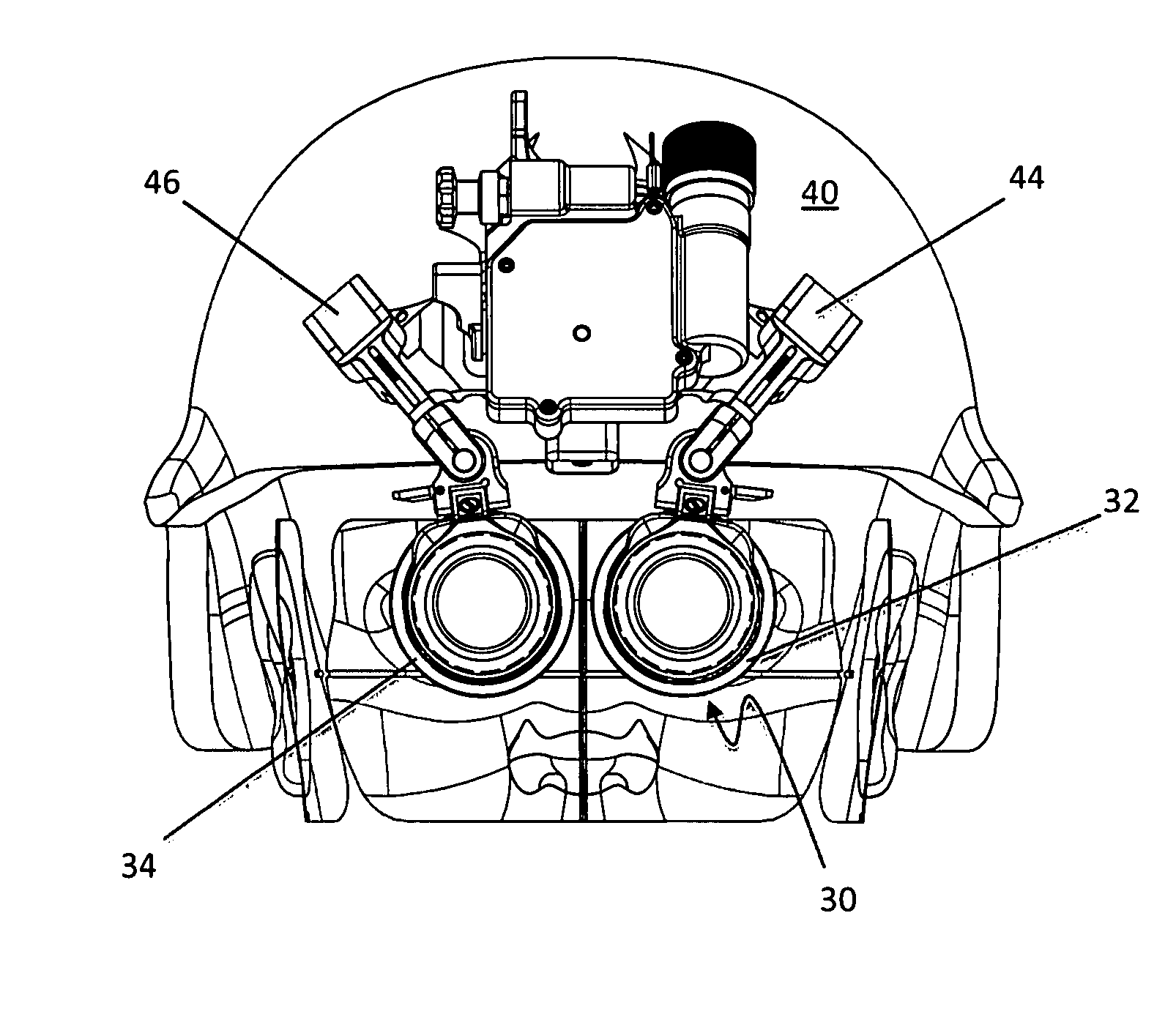
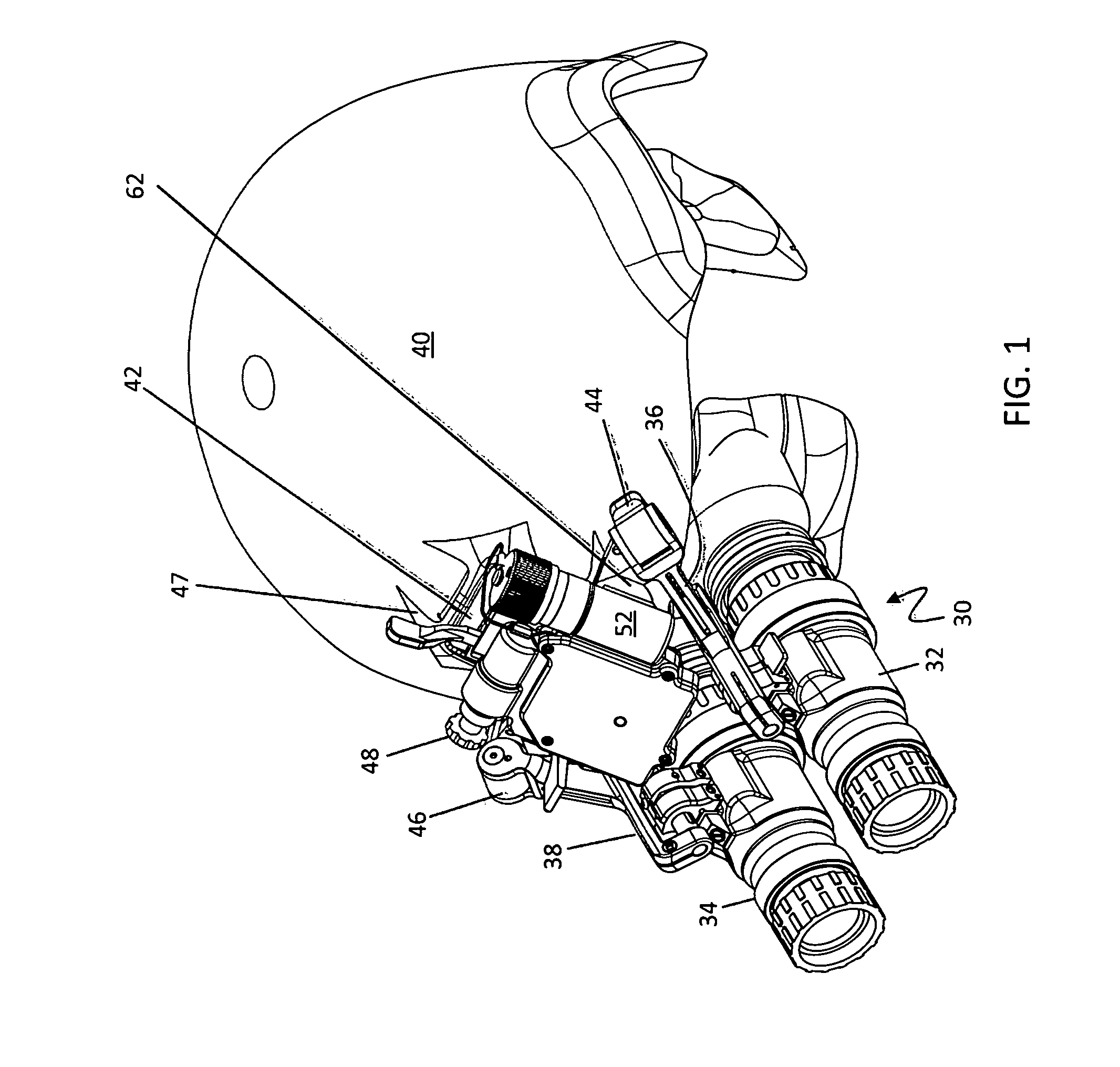
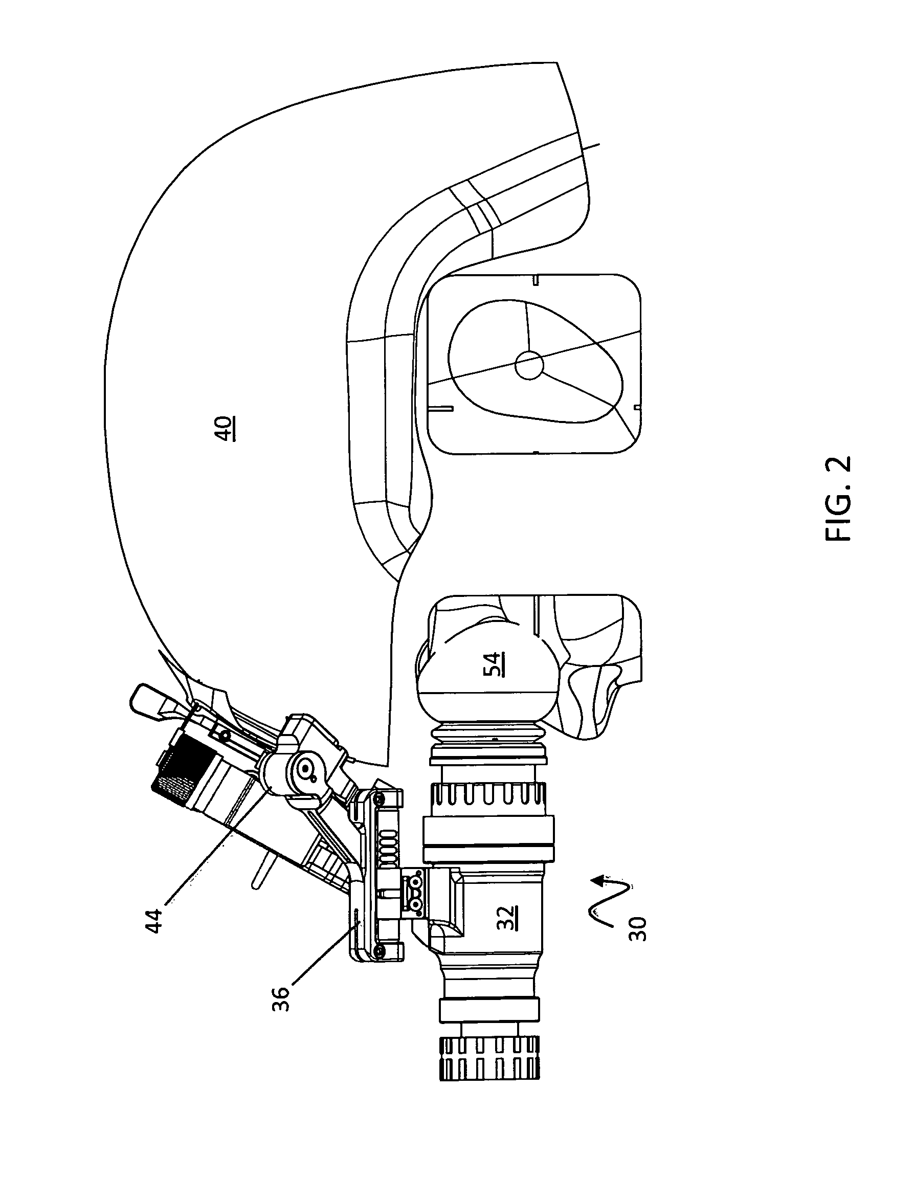
[0036]Referring to FIG. 1, a binocular system 30 is shown attached to a helmet 40 that may be worn by a user. The binocular system 30 includes a first monocular 32 and a second monocular 34 that may be manipulated independently, as described in more detail elsewhere herein. The monoculars 32, 34 may be night vision devices, thermal imaging devices, conventional optical magnifying devices, electronic display devices that provide at least some visual information according to an electronic signal provided thereto (not illustrated in FIG. 1) and / or any device that provides useful visual information to a user. In some embodiments, it is possible for each of the monoculars 32, 34 to provide different types of visual information. For example, the monocular 32 could be a night vision device while the monocular 34 is a conventional optical magnifying device. In other embodiments, both of the monoculars 32, 34 are the same type of device, such as both being night vision devices. It is also po...


PUM


Abstract

A binocular system includes a first monocular, a second monocular, a first arm coupled to a base plate via a first hinge and coupled to the first monocular, and a second arm coupled to the base plate via a second hinge and coupled to the second monocular. Each of the monoculars rotates about a corresponding one of the hinges along an axis of rotation that is not parallel to an axis of collimation of each of the monoculars. The monoculars are collimated when rotated into a deployed position. The binocular system may also include a mounting bracket coupled to the base plate, a tilt base, interposed between the mounting bracket and the base plate and a tilt lever, having a cam that is operatively engaged with the tilt base, where actuation of the lever causes the base plate to tilt with respect to the mounting bracket.

Description

CROSS-REFERENCE TO RELATED APPLICATIONS[0001]This application is a continuation-in-part of U.S. patent application Ser. No. 12 / 931,555 filed on Feb. 4, 2011 (pending), which is incorporated by reference herein.BACKGROUND OF THE INVENTION[0002]1. Technical Field[0003]This application relates to the field of vision devices, and more particularly to the field of stereoscopic vision devices that are adjustable.[0004]2. Description of Related Art[0005]Conventional helmet mounted vision devices may be stored in a raised position when the devices are not being used. In such a position, the devices remain attached to the helmet, but are flipped vertically (stowed) so that the devices are significantly above the top of the helmet. This makes the wearer more visible, which may not be desirable in certain situations (e.g., in military situations). Additionally, such a configuration may make it difficult to move in some situations and may put unnecessary strain on a user when the components are...

Claims


Application Information

Patent Timeline
Patent Type & Authority Patents(United States)
IPC IPC(8): G02B23/18G02B23/12G02B23/00G02B27/01
CPCG02B23/18G02B2027/0132G02B27/0176G02B23/125G02B2027/0138
Inventor RIVKIN, MAXIMNARKEVICIUS, GINTAUTAS
Owner N VISION OPTICS
Why Eureka
Try Eureka