Monolithic microwave integrated circuits (MMICs) having conductor-backed coplanar waveguides and method of designing such MMICs

a technology of conductor-backed coplanar waveguides and integrated circuits, which is applied in the direction of electrical apparatus contruction details, association of printed circuits non-printed electric components, transistors, etc., can solve the problems of limited space for connection between the cpw local ground and the backside signal ground, affecting the electrical performance of the mmic, and being impractical for 100 um thick substrates

Active Publication Date: 2014-10-21
RAYTHEON CO
View PDF9 Cites 222 Cited by
  • Summary
  • Abstract
  • Description
  • Claims
  • Application Information

AI Technical Summary

Problems solved by technology

In the case where substrate vias are not used such as with Silicon Carbide (SiC) or diamond, the space for connection between the CPW local ground and the backside signal ground is limited and sometimes the connections may be available only at the edges of the chip.
The parallel plate mode generates unwanted resonances and other deleterious electromagnetic coupling effects that affect electrical performance of the MMIC.
This practice can be adequate for thick 500 um substrates, but it is impractical for 100 um thick substrates because it imposes too many restrictions on the range of dimensions available for design.
The corresponding lines would be too narrow and add significant loss to a CPW tuning network, degrading MMIC performance.
In the latter case the solution of the analysis is specific to the particular configuration and generally not suitable for design purposes.
Thus neither approach is capable of representing the currents of conductor backed CPW circuits accurately.

Method used


Image

  • Monolithic microwave integrated circuits (MMICs) having conductor-backed coplanar waveguides and method of designing such MMICs
  • Monolithic microwave integrated circuits (MMICs) having conductor-backed coplanar waveguides and method of designing such MMICs
  • Monolithic microwave integrated circuits (MMICs) having conductor-backed coplanar waveguides and method of designing such MMICs

Examples


Embodiment Construction

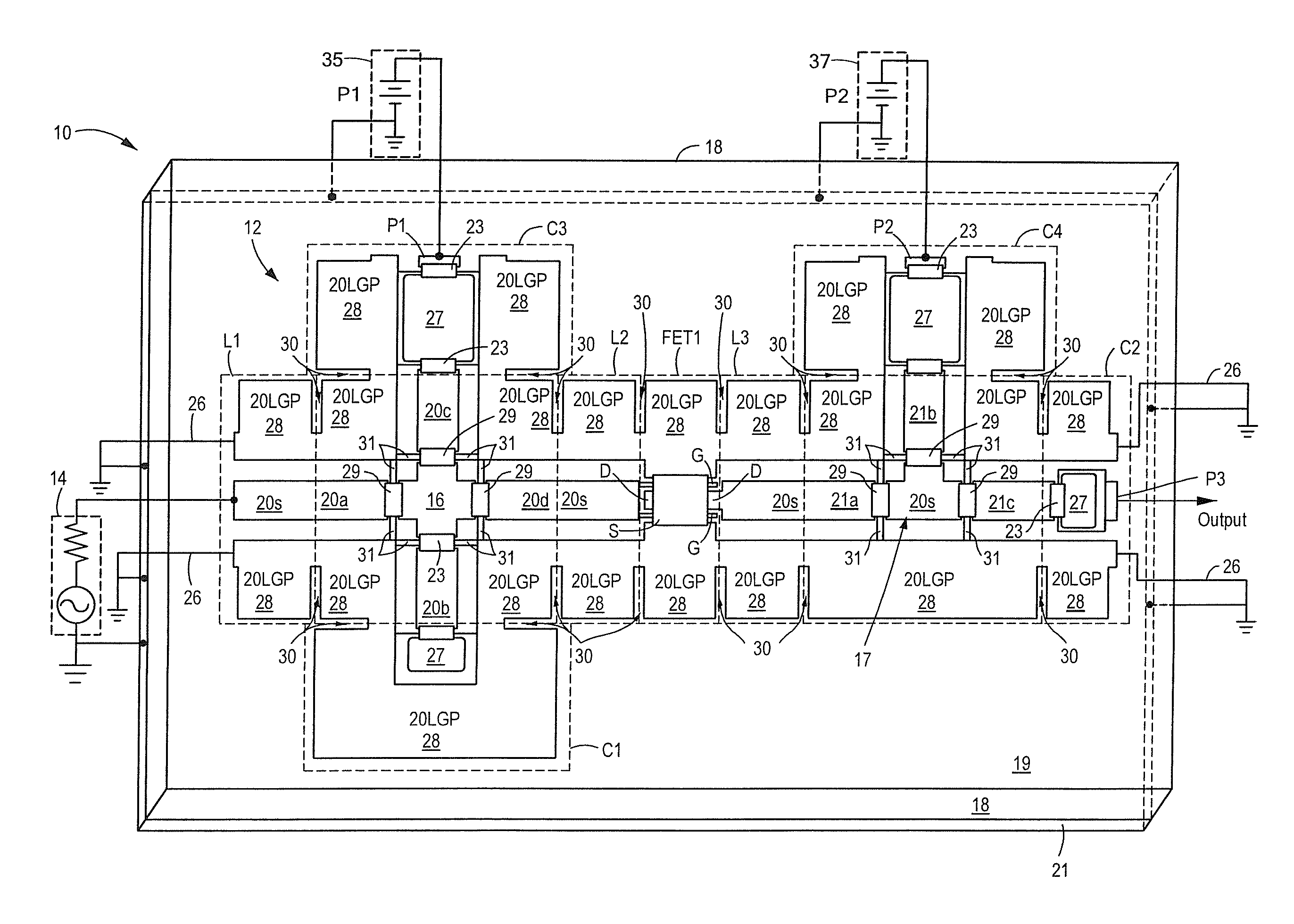
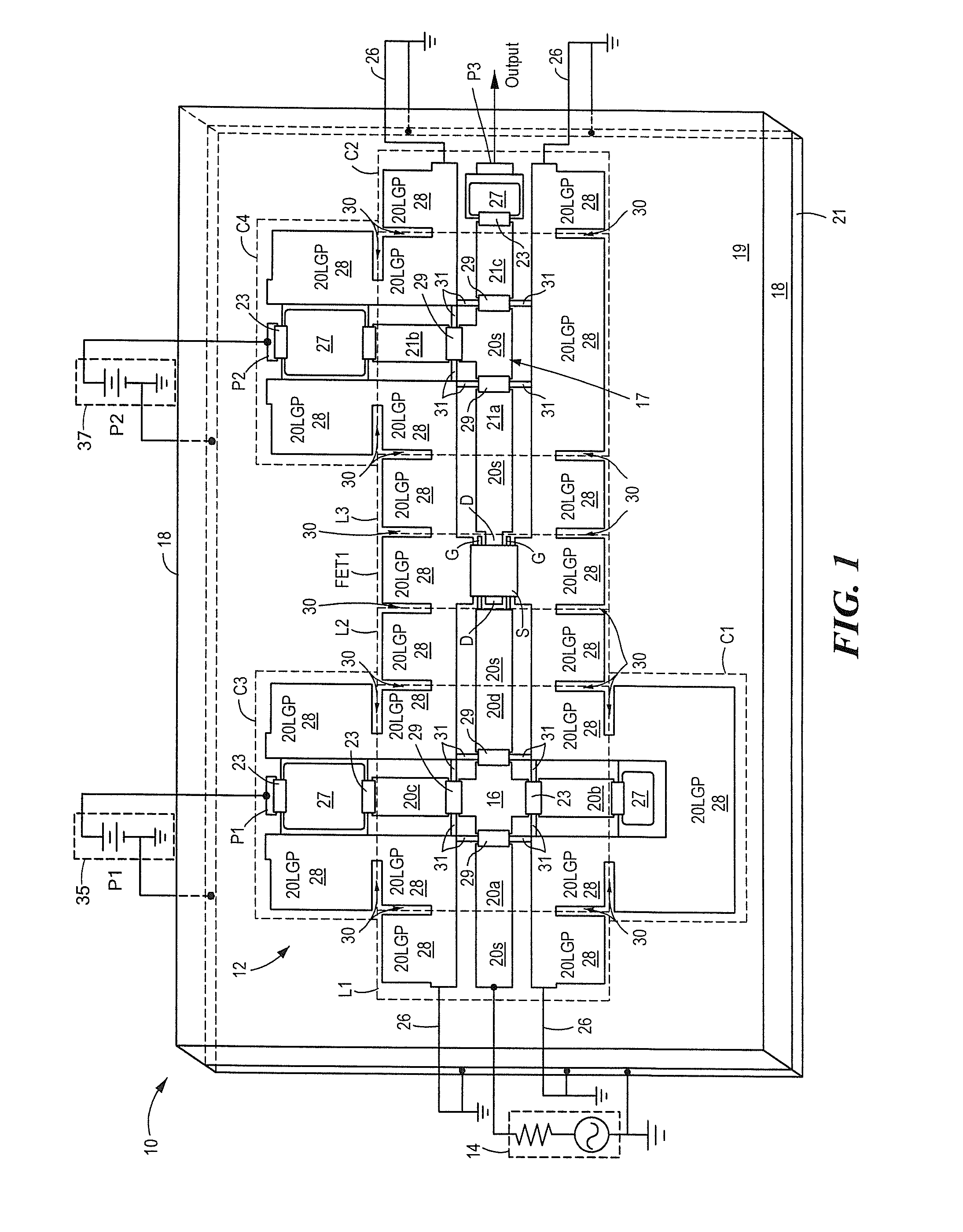
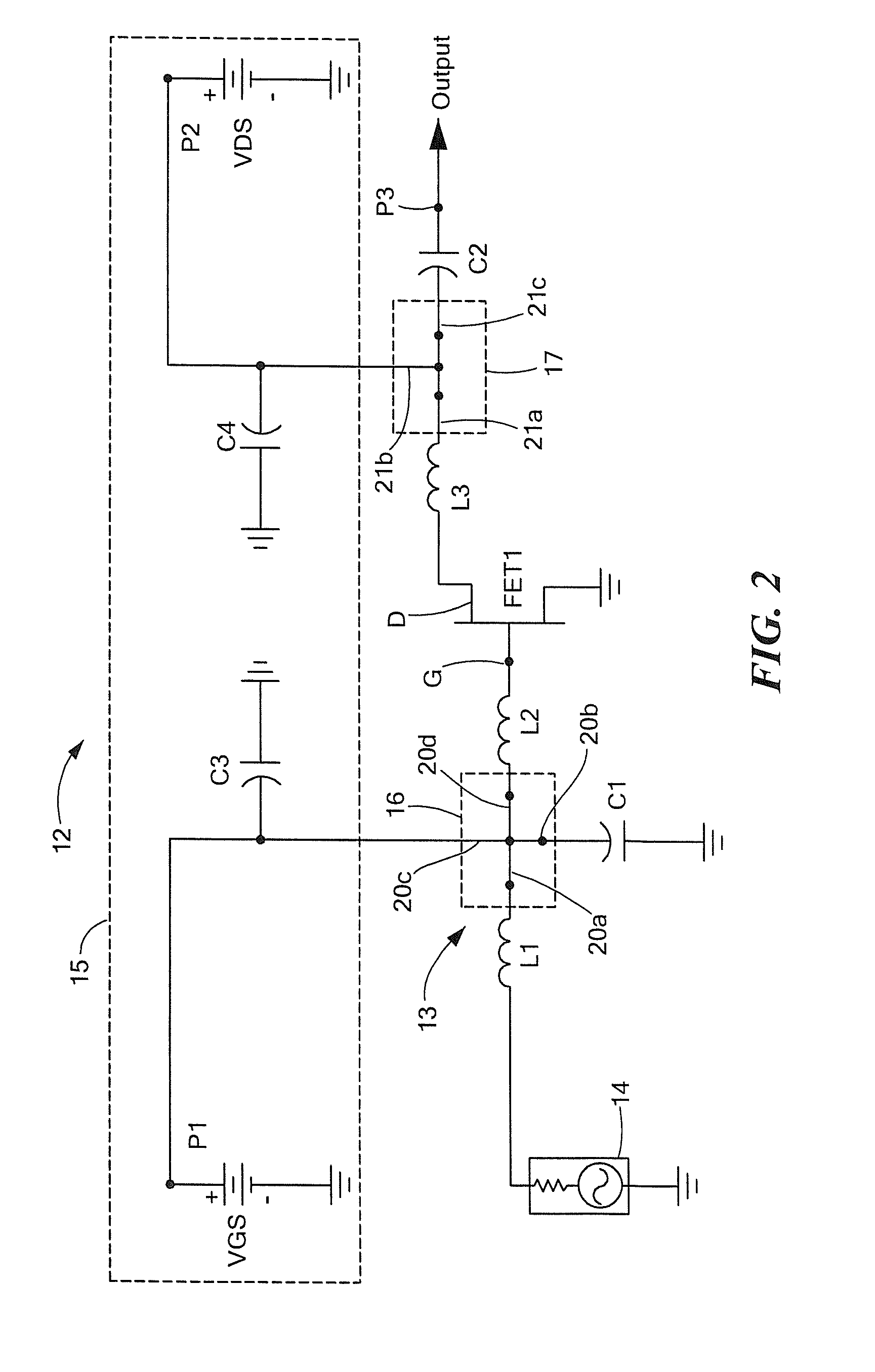
[0023]Referring now to FIG. 1, a monolithic microwave integrated circuit (MMIC) 10 of an exemplary electrical circuit 12, here for example an amplifier represented by the simplified schematic circuit in FIG. 2, is shown. Referring to FIG. 2, here, the amplifier 12 includes a FET (FET1) having the gate electrode (G) hereof coupled to a radio frequency source 14 through a network 13 having a pair of serially coupled inductors L1, L2 and a shunt capacitor C1. One electrode of the capacitor and one electrode (here the source electrode (S)) of the FET1 are connected to ground as shown. It is noted that the inductor L1, inductor L2 and the capacitor C1 are interconnected at a cross-shaped junction 16. The output electrode, here the drain electrode (D) of the FET is coupled to an output OUTPUT through an inductor L3 and serially coupled capacitor C2, as shown.

[0024]A DC biasing network 15 is included. The DC biasing network 15 includes a gate supply VGS and a drain supply VDS. The gate sup...


PUM


Abstract

A MMIC having: a substrate; a plurality of active and passive electrical elements disposed on a top surface of the substrate; a plurality of coplanar waveguide transmission line sections disposed on the top surface of the substrate for electrically interconnecting the active and passive electrical elements; an electrical conductor disposed on a bottom surface of the substrate under the coplanar waveguide section. Edges of ground plane conductors of the coplanar waveguide (CPW) sections have slots therein in regions thereof connected to the active and passive devices. The design of such circuit includes mathematical models of the CPW with the pair of local ground planes and the strip conductor thereof have relatively narrow connectable ports.

Description

STATEMENT REGARDING FEDERALLY SPONSORED RESEARCH[0001]This invention was made with Government support under Contract No. FA8650-09-C-5404 awarded by the Department of the Air Force. The Government has certain rights in this invention.TECHNICAL FIELD[0002]This disclosure relates generally to monolithic microwave integrated circuits (MMICs) having conductor-backed coplanar waveguides and method of designing such MMICs.BACKGROUND AND SUMMARY[0003]As is known in the art, many Monolithic Microwave Integrated Circuit (MMIC) structures use Coplanar Waveguide (CPW) to interconnect various electrical devices and elements of the circuit. The CPW has both the strip conductor and the adjacent ground plane conductors on the same side of a substrate where the electrical devices and elements of the circuit are formed. These ground plane conductors provide the local ground plane for the circuit. The backside of the MMIC substrates provided with a metal, such as thick electro-plated gold, to enable ...

Claims


Application Information

Patent Timeline
Patent Type & Authority Patents(United States)
IPC IPC(8): H05K1/18H01L27/06H05K7/00H05K1/00H01Q5/00
CPCH01L27/0629H01Q5/0058H01L27/0605H01Q5/371
Inventor TYHACH, MATTHEW C.COLOMB, FRANCOIS Y.
Owner RAYTHEON CO
Why Eureka
Try Eureka