Poly-metal hose reel water system

a technology of hose reels and hoses, applied in the direction of hose connections, couplings, thin material processing, etc., can solve the problems of inability to easily access the location of clips, poor installation effect, wear and tear of o-rings, etc., to achieve quick and easy actuation of the clip assembly, quick and easy removal of the inlet conduit, and easy installation

Active Publication Date: 2014-10-28
IAMS
View PDF13 Cites 3 Cited by
  • Summary
  • Abstract
  • Description
  • Claims
  • Application Information

AI Technical Summary

Benefits of technology

[0008]An inlet conduit assembly for a hose reel assembly as recited in the claims below includes a clip assembly that is structured to be accessible from the outer side of the frame assembly. Further, the clip assembly is structured to be operated without the use of tools. In this configuration, a user may quickly and easily actuate the clip assembly to release or engage the inlet conduit. Thus, a user may quickly and easily remove the inlet conduit so that the O-rings may be replaced or for other reasons. Further, when the user wished to install the inlet conduit, the installation is also easily accomplished.
[0009]In one embodiment, the clip assembly includes a pivoting clip body having a clip structure that is, preferably, two pincer-like fingers. The body is coupled to the hose reel frame assembly and structured to pivot. The clip structure fingers extend in the same general plane that the clip body pivots in. The inlet conduit, which is preferably a circular tube, includes a retaining clip groove extending at least partially circumferentially thereabout. When the inlet conduit is fully inserted into the basket assembly conduit, the retaining clip groove is disposed in the plane of the clip body rotation. Thus, the clip body may be pivoted between a first position, wherein the clip structure does not engage the inlet conduit body retaining clip groove, and a second position, wherein the clip structure engages the inlet conduit body retaining clip groove. When the clip structure engages the inlet conduit body retaining clip groove, the inlet conduit is, essentially, prevented from being moved axially. That is, when the clip structure engages the inlet conduit body retaining clip groove the inlet conduit and the basket assembly conduit form a passage from the lateral side of the hose reel to a basket surface outlet.

Problems solved by technology

In this configuration, the O-rings are subject to wear and tear as the O-rings are the elements at the interface between the inlet conduit and the basket assembly conduit.
Initially, the coupling devices were not structured to allow the user to separate the inlet conduit from the basket assembly conduit.
These clips, however, have been disposed in difficult to access locations, e.g., between a basket assembly hub and the frame assembly.

Method used


Image

  • Poly-metal hose reel water system
  • Poly-metal hose reel water system
  • Poly-metal hose reel water system

Examples


Embodiment Construction

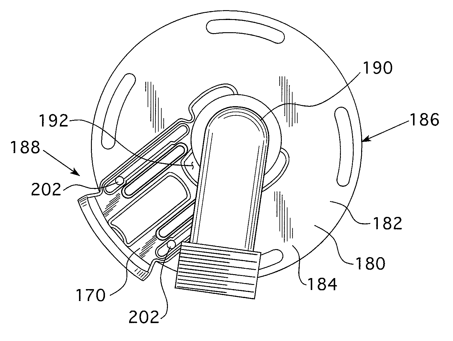
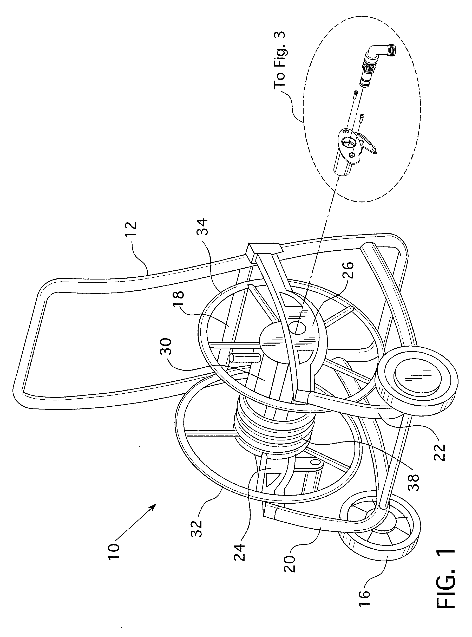
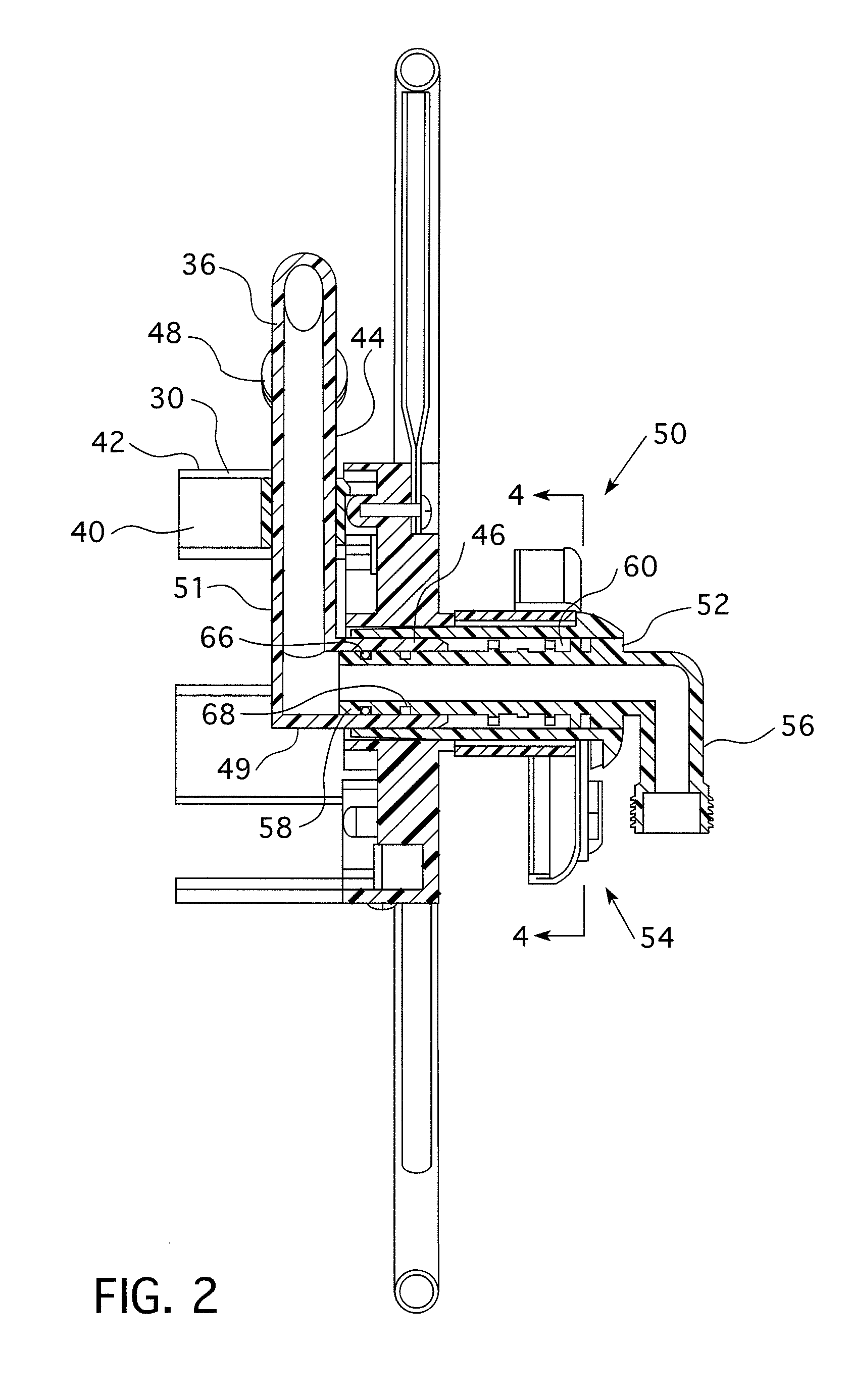
[0017]As used herein, “coupled” means a link between two or more elements, whether direct or indirect, so long as a link occurs.

[0018]As used herein, “directly coupled” means that two elements are directly in contact with each other.

[0019]As used herein, “fixedly coupled” or “fixed” means that two components are coupled so as to move as one while maintaining a constant orientation relative to each other. The fixed components may, or may not, be directly coupled.

[0020]As used herein, the word “unitary” means a component is created as a single piece or unit. That is, a component that includes pieces that are created separately and then coupled together as a unit is not a “unitary” component or body.

[0021]As used herein, “temporarily coupled” means that two components are coupled in a manner that allows for the components to be easily decoupled without damaging the components.

[0022]As used herein, “correspond” indicates that two structural components are sized to engage each other with...


PUM


Abstract

An inlet conduit assembly for a hose reel assembly includes a clip assembly that is structured to be accessible from the outer side of the frame assembly. The clip assembly is structured to be operated without the use of tools. The clip assembly, essentially, prevents the inlet conduit assembly from being moved axially once installed. In this configuration, a user may quickly and easily actuate the clip assembly to release or engage the inlet conduit assembly. Thus, a user may quickly and easily remove the inlet conduit assembly.

Description

CROSS REFERENCE TO RELATED APPLICATION[0001]This application is a Continuation-In-Part Application of U.S. Ser. No. 12 / 270,891, filed Nov. 14, 2008, which claims priority to U.S. Provisional Patent Application Ser. No. 61 / 002,997, filed Nov. 14, 2007 entitled Metal Hose Reel Water System.BACKGROUND OF THE INVENTION[0002]1. Field of the Invention[0003]This invention relates to hose reels and, more specifically, to an inlet assembly that may be easily accessed.[0004]2. Background Information[0005]A hose reel typically includes a portable frame assembly that supports a basket assembly. The basket assembly has a central barrel and two end hubs. The basket assembly is structured to have a hose wound thereabout and is rotatably coupled to the frame assembly. The basket assembly also includes one or more conduits structured to couple an external hose to the basket assembly hose. One conduit, the basket assembly conduit, has an inlet end disposed along the axis of rotation of the basket ass...

Claims


Application Information

Patent Timeline
Patent Type & Authority Patents(United States)
IPC IPC(8): B65H75/34B65H75/44B65H75/40
CPCB65H2701/33B65H75/403B65H75/4478Y10T137/6954Y10T137/6918Y10T137/6929Y10T137/6958F16L37/1225
Inventor ARCATI, PETER
Owner IAMS
Why Eureka
Try Eureka