LED light for examinations and procedures

a technology of led light and examination, applied in the field of illumination, can solve the problems of limiting the effectiveness of the system, preventing accessibility, cumbersome users, etc., and achieve the effect of reducing floor clutter, maximum accessibility, and convenient location

Active Publication Date: 2014-10-28
MIDMARK
View PDF6 Cites 62 Cited by
  • Summary
  • Abstract
  • Description
  • Claims
  • Application Information

AI Technical Summary

Benefits of technology

[0008]Embodiments of the invention not only focus on designing an examination light, but are also focused on the interaction between a user and the light. Embodiments of the examination light provide mounting locations that allow proper reach of the light source, provide a home storage position, and assist in reducing floor clutter by attaching the light to an examination chair or examination table. Mounting directly to the examination chair or table allows for maximum accessibility to the patient and may aesthetically blend in with the chair or table, which also may assist in making the exam and procedure rooms more inviting to a patient.
[0009]In some embodiments, the location of the power switch is on the light head. This location may assist in eliminating the need for the user to reach away from the light head, which may be uncomfortable for the provider and patient. A recessed location of the power switch, in some embodiments, may make it easy to locate and may assist in preventing accidental activation of the switch.
[0010]The optical system, in some embodiments, allows light intensity and uniformity to be met in a very short distance while using a LED as the light source, thus avoiding some of the issues related to contemporary halogen bulb lights. This short distance allows for a smaller light head, which adds to the ergonomics of the design and assists in positioning the light without obstructing the view of the healthcare provider. The LED light source produces a light beam that generally does not generate heat at the illumination site. Additionally, a predicted life for the LED is approximately a 50,000 hour life versus a few thousands of hours of their counterpart halogen bulbs.
[0011]Embodiments may also include a controller which is configured to drive more current through the LED effectively generating more foot-candles or lux as the spot size diameter is increased. This may assist in offsetting any loss in light intensity allowing for a system that can maintain intensity throughout the spot size range. A healthcare provider may now be able to increase the spot size without suffering a loss of light intensity.

Problems solved by technology

It is equally important that once positioned, the light does not drift from this location, which can cause inconvenience especially when working in a sterile field.
Contemporary examination lights are generally not designed specifically for interaction with examination and procedure chairs and tables, limiting their effectiveness when used as a system.
The contemporary exam lights are typically caster based, wall mounted, or ceiling mounted making them cumbersome for users and in some cases preventing accessibility to a patient.
Because of the halogen bulb, some lights require larger product envelopes.
Furthermore, the halogen bulbs utilized in the contemporary lights generally offer only hundreds to a few thousand hours of life.
Blown bulbs may be costly and inconvenient especially if the failure of the bulb occurs in the middle of an examination or procedure.
Moreover, as these light sources are manipulated to adjust a spot size of the light, the spots generally lose intensity as the spot size is increased, having health care professionals choose between more intense light or a larger spot of light.
Heat generated from contemporary lamps can become uncomfortable for both the provider and patient.
Some contemporary lamps attempt to place the light source in the base of the light, away from the provider and the patient, but these configurations then require transmitting the light from the base of the light to the lamp head as well as fans or other heat dissipation components which are a source of noise and add cost to the overall system.

Method used


Image

  • LED light for examinations and procedures
  • LED light for examinations and procedures
  • LED light for examinations and procedures

Examples


Embodiment Construction

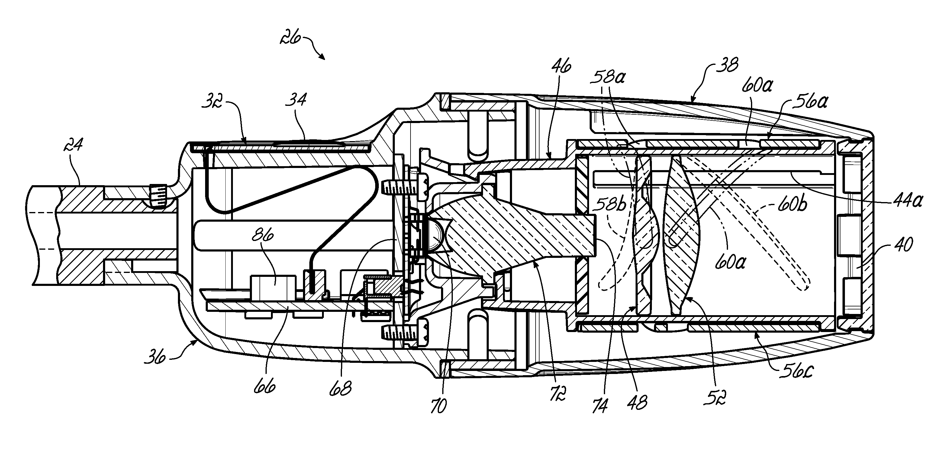
[0025]Embodiments of the invention provide an examination light that delivers lighting with proper intensity, color temperature and uniformity to assist in enabling a medical provider in providing proper diagnoses. Embodiments allow the light to be used in multiple types of examinations and procedures by providing an adequate reach and positioning to assist in illuminating any part of the body without drifting from its location. Embodiments of the invention also allow for the ability to adjust the spot size from a minimum range to a maximum range assisting the provider in being able to direct light only where needed. Additionally, embodiments of the invention also provide an auto-intensity functionality, driving more light to an increased spot size, assisting in minimizing intensity roll-off.

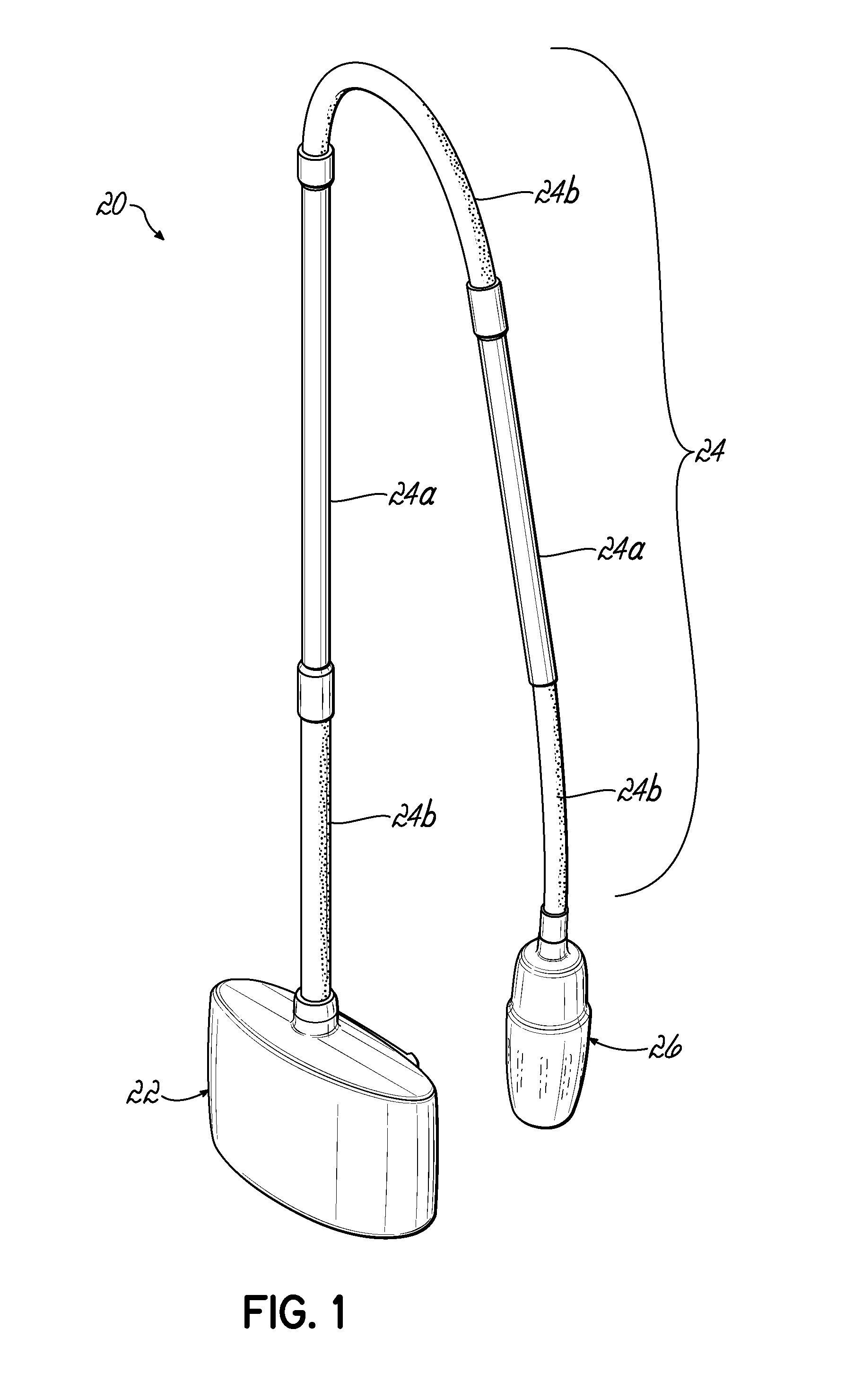
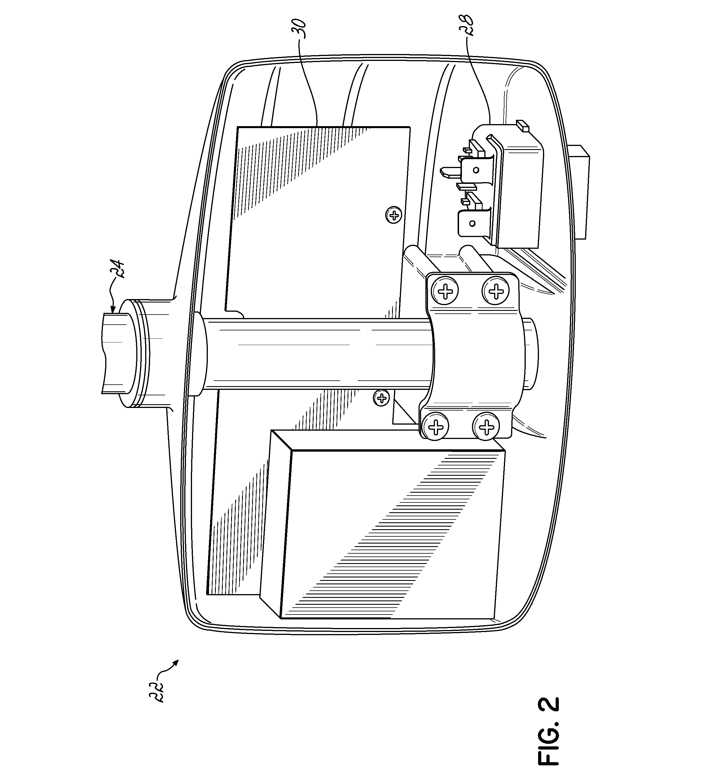
[0026]Turning now the embodiment of the examination light 20 in FIG. 1, the light 20 includes a base component 22, an arm 24 with both rigid 24a and flexible 24b sections, and a lamp head 26. Th...


PUM


Abstract

A light is provided having a base unit, an arm extending from the base unit, and a lamp head coupled to the arm. The lamp head includes an LED configured to provide light based on an input drive current, an optical mixing element configured to collect the light produced by the LED and a zoom lens configured to adjust an output size of a spot generated by the light collected in the mixing element. A controller receives DC power from the base unit through the arm. The controller is configured to set the input drive current for the LED to control an output light density of the spot in response to an operator selected input and configured to adjust the output light density of the spot in response to a change in the size of the spot.

Description

CROSS REFERENCE[0001]This application is a submission under 35 U.S.C. §371 of International Patent Application No. PCT / US2011 / 024850 filed Feb. 15, 2011 (pending), which claims priority to U.S. Provisional Patent Application Ser. No. 61 / 304,848, filed Feb. 16, 2010, the disclosures of which are incorporated by reference herein in their entirety.FIELD OF THE INVENTION[0002]This application relates generally to the field of illumination, and more particularly to an LED illumination device for use by a physician or health care provider.BACKGROUND OF THE INVENTION[0003]Health care providers, during examinations and procedures, need additional lighting to better diagnose and treat different health conditions. It is important for lighting to have proper intensity, color temperature, and uniformity so that the provider is not mislead when making a diagnosis during the examination or procedure. The examination light may be used in multiple types of examinations and procedures; therefore, it...

Claims


Application Information

Patent Timeline
Patent Type & Authority Patents(United States)
IPC IPC(8): F21V7/00F21V21/32F21V23/04H05B33/08H05B37/02F21W131/20F21V17/02F21S6/00G02B15/14F21V5/00F21V14/06F21V5/04F21Y101/02H05B44/00
CPCG02B15/14F21V21/32H05B37/02F21Y2101/02F21V23/0442F21V5/008F21V14/06H05B33/0854F21V23/04F21V17/02F21W2131/20F21S6/003F21V23/0457F21V7/0091F21V5/04F21Y2115/10H05B45/10
Inventor KREITZER, MELVYN H.MONTGOMERY, KEVIN M.MOSKOVICH, JACOBRAU, BRIAN D.TREON, THOMAS L.
Owner MIDMARK
Why Eureka
Try Eureka