Resistive touch panel with improved termination

a technology of resistive touch panel and termination, applied in the field of resistive matrix touch panel, can solve the problems of serial sampling of present-day solutions, and achieve the effects of reducing the overall effect of the rc network, increasing the available signal, and increasing the amplitude signal

Inactive Publication Date: 2014-10-28
SMSC HLDG
View PDF1 Cites 0 Cited by
  • Summary
  • Abstract
  • Description
  • Claims
  • Application Information

AI Technical Summary

Benefits of technology

[0011]In one set of embodiments, a resistive sensing circuit may comprise some row receiver lines that are terminated to VDD (a supply voltage level) instead of voltage reference (e.g. ground), to greatly increase the available signal for sensing. An effective “guard band” is thereby created around the signals being sampled, reducing the overall effect of the RC network because 3 are now in parallel, and resulting in a net effect of a much higher amplitude signal. In addition, the termination resistor may be increased to include the currently used series resistor to increase the signal amplitude. Since the net resistance to ground remains the same, there is little or no effect on the overall impedance, while improving both the DC and transient response of the TP. The signal amplitude that is thereby produced is higher than in most present day solutions, which use a 10 kΩ resistor to terminate the sampled signal, after applying as much as 50 kΩ in series to equalize the signals, producing a 6:1 attenuator, and slowing the impulse response of the TP.
[0012]In one set of embodiments, with the methods combined—i.e. some row receiver lines terminated to VDD, and the termination resistor increased—the sampling system may become capable of sampling eight rows in parallel. Present day solutions are limited to sampling channels serially. Thus, various embodiments of the improved resistive TP increase the overall bandwidth of the system while allowing each analog-to-digital (ADC) channel to operate slower. One specific improvement is the compressed response of the system. While present day solutions offer 10%-40% signal strength at the row receiver ADC, the signal strength in various embodiments of the improved TPs disclosed herein increases to 20%-60%. This greatly simplifies the signal processing, and reduces the analog circuit complexity. The termination and bias changes also result in improvements in the overall system performance and AC response of the system, as the parallel impedances to ground reduce the overall impedance.

Problems solved by technology

Present day solutions are limited to sampling channels serially.

Method used


Image

  • Resistive touch panel with improved termination
  • Resistive touch panel with improved termination
  • Resistive touch panel with improved termination

Examples


first embodiment

DC Analysis in a First Embodiment

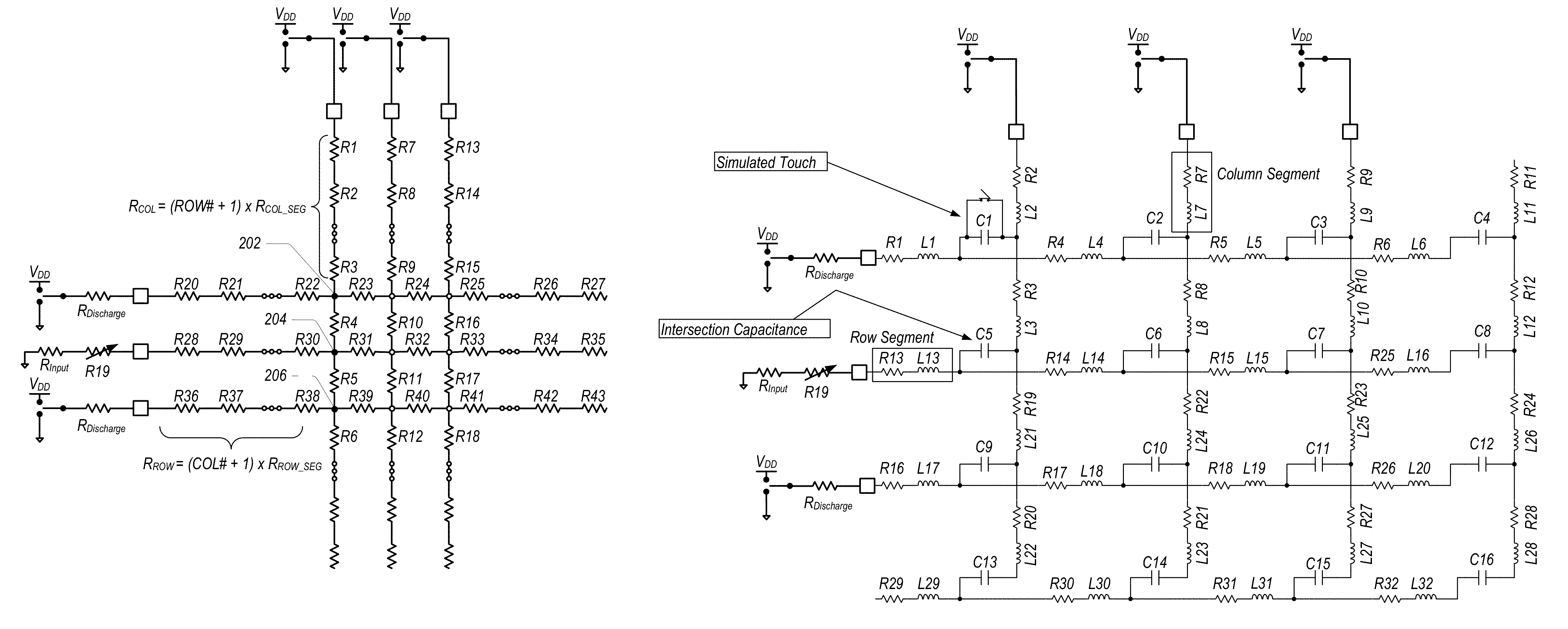
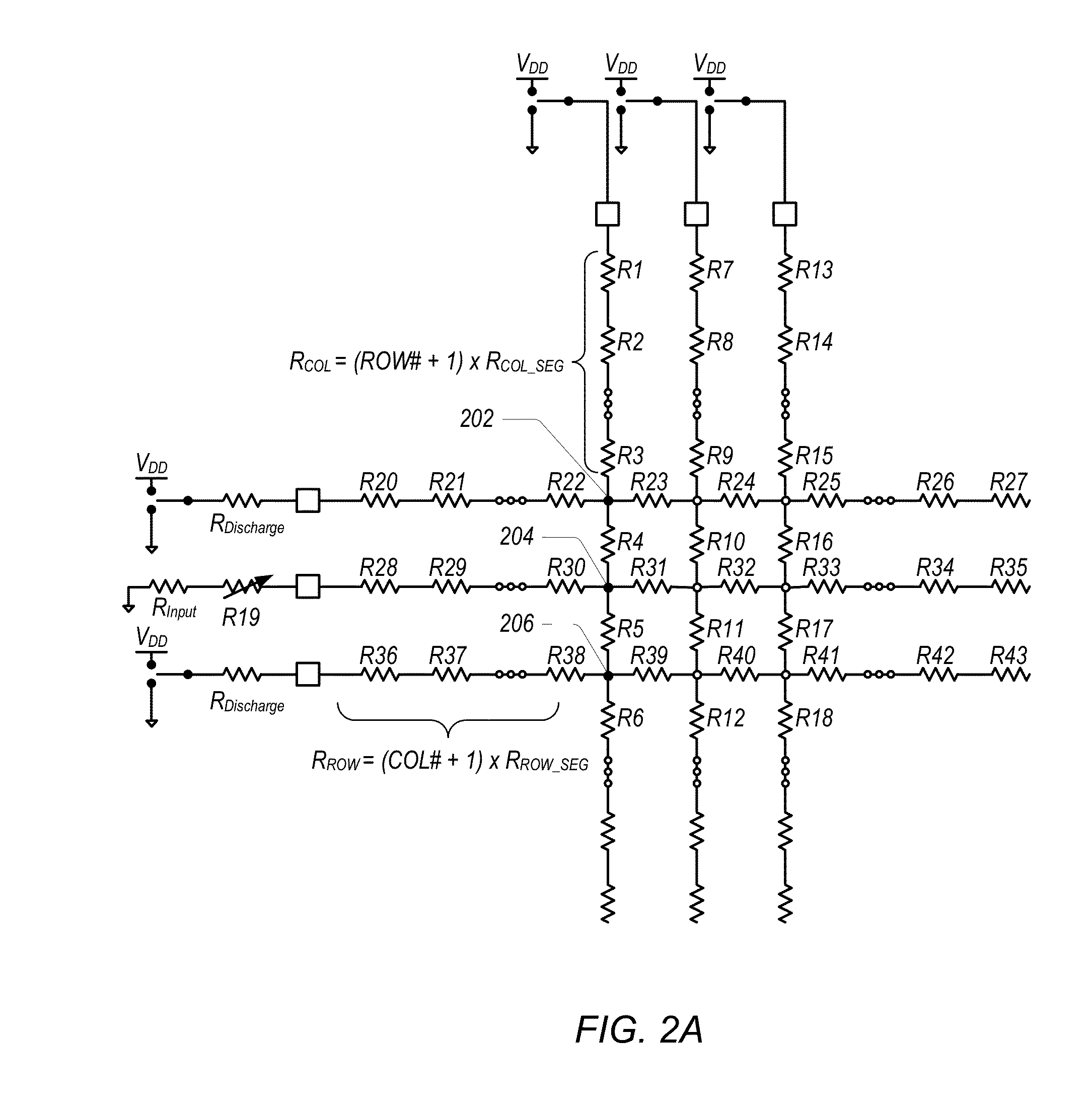
[0065]In one embodiment, a TP with a ˜16:9 aspect ratio using a total of 252 input / output (I / O) pins for 156 rows and 96 columns may be selected. The diagram in FIG. 2B shows a pertinent portion of the assumed panel, and how to calculate the resistance values between the sites being touched and the edge of the column drive or row receiver. In FIG. 2A, the shaded nodes at the resistor intersections (nodes 202, 204, 206) indicate points where the TP (matrix) is touched. The open nodes (or open circles) at the resistor intersections indicate points where the TP (matrix) remains untouched. As shown in FIG. 2B, a simulated touch is represented by a short across the intersection capacitance of the intersections in the driven column. Analysis is provided for a single column driven, and multiple touches occurring on that column. The variable resistor R19 is not included in this analysis.

[0066]The analysis shows the detrimental effects of terminations to grou...

second embodiment

DC Analysis in a Second Embodiment

[0076]In a second embodiment, a TP with a 4:3 aspect ratio using a total of 250 I / O pins for 103 rows and 137 columns may be selected, with a maximum expected resistance of 100 kΩ. The TP pattern is assumed to be square, meaning the resistance per segment in either row or column are equal. Again, the diagrams in FIGS. 2A and 2B show the assumed panel (simplified and in more detail, respectively), and how to calculate the resistance values between the sites being touched and the edge of the column drive or row receiver. As before, in FIG. 2A, nodes 202, 204, and 206 at the resistor intersections indicate points where the TP (matrix) was touched, and the unshaded nodes at the resistor intersections indicate points where the TP (matrix) was untouched. As indicated in FIG. 2B, a short across the intersection capacitance corresponds to a simulated touch. Analysis is again provided for a single column driven, with multiple touches occurring on that column...


PUM


Abstract

A resistive sensing touch panel may include row receiver tracks and column drive tracks. A controller may send and receive control signals and sense signals, respectively, to and from the resistive touch panel. The resistive touch panel may provide sense signals when a touch of the panel is detected. The sense signals may be sampled on a number of rows. When sampling a given row, the controller may change the termination of that row by coupling the end of the sampled row to a resistor having a higher value then terminating resistors coupled to the end of non-sampled rows that are adjacent to the sampled row. The controller may further pull the terminating resistors coupled to the end of the non-sampled adjacent rows to a supply rail voltage while the sampled row is being sampled.

Description

PRIORITY CLAIM[0001]This application claims priority to U.S. Provisional Application Ser. No. 61 / 531,534 titled “Resistive Touch Panel” filed Sep. 6, 2011, whose inventor is Lynn R. Kern, and further claims priority to U.S. Provisional Application Ser. No. 61 / 587,446 titled “Resistive Touch Panel with Improved Termination” filed Jan. 17, 2012, whose inventor is also Lynn R. Kern, and both of which are hereby incorporated by reference in their entirety as though fully and completely set forth herein.BACKGROUND OF THE INVENTION[0002]1. Field of the Invention[0003]This invention relates generally to the field of touch panel design, and more particularly to the design of a resistive matrix touch panel.[0004]2. Description of the Related Art[0005]It's been a high priority for many electronics manufacturers to offer user interfaces that are powerful yet simple to use, while remaining highly reliable. Some of the more popular interfaces have been touchscreens and touchpads. Touchscreens an...

Claims


Application Information

Patent Timeline
Patent Type & Authority Patents(United States)
IPC IPC(8): G06F3/045G06F3/041
CPCG06F3/0416G06F3/045
Inventor KERN, LYNN, R.
Owner SMSC HLDG
Why Eureka
Try Eureka