Optical lens system

a technology of optical lens and optical lens frame, which is applied in the field of optical lens frame system, can solve the problems of poor image edge quality, high refractive material use, and increase manufacturing cos

Active Publication Date: 2014-10-28
GLORY SCI
View PDF8 Cites 12 Cited by
  • Summary
  • Abstract
  • Description
  • Claims
  • Application Information

AI Technical Summary

Benefits of technology

[0006]The primary objective of the present invention is to provide an optical lens system applicable to electronic products which require the use of micro camera, such as mobile phone, notebook, and tablet computer, etc. The optical lens system of the present invention is compact and has a wide angle of view, a small F number with high image quality and low sensitivity to assembly tolerance, and a low material cost.

Problems solved by technology

For another example, the optical lens systems disclosed in U.S. Pat. Nos. 8,284,291, 8,390,941 and 8,488,259 all have a smaller F number, but is provided with more than two lens elements which are made of high refractive material, and the use of high refractive material will increase the manufacturing cost.
However, the chief ray angle at the edge of the image is too large, which adversely affects the brightness and color at the peripheral of the image, namely, resulting in a poor image edge quality.

Method used


Image

  • Optical lens system
  • Optical lens system
  • Optical lens system

Examples


first embodiment

[0054]The equation for the aspheric surface profiles of the first embodiment is expressed as follows:

[0055]z⁡(h)=ch21+1-(1+k)⁢c2⁢h2+A4⁢h4+A6⁢h6+A8⁢h8+A10⁢h10+A12⁢h12+A14⁢h14+⁢⋯

[0056]z represents the distance of a point on the aspheric surface at a height h from the optical axis relative to a plane perpendicular to the optical axis at the vertex of the aspheric surface;

[0057]c is a paraxial curvature equal to 1 / R (R: a paraxial radius of curvature);

[0058]h represents a vertical distance from the point on the curve of the aspheric surface to the optical axis;

[0059]k represents the conic constant;[0060]A4, A6, Ag, A10, A12, A14 . . . : represent the high-order aspheric coefficients.

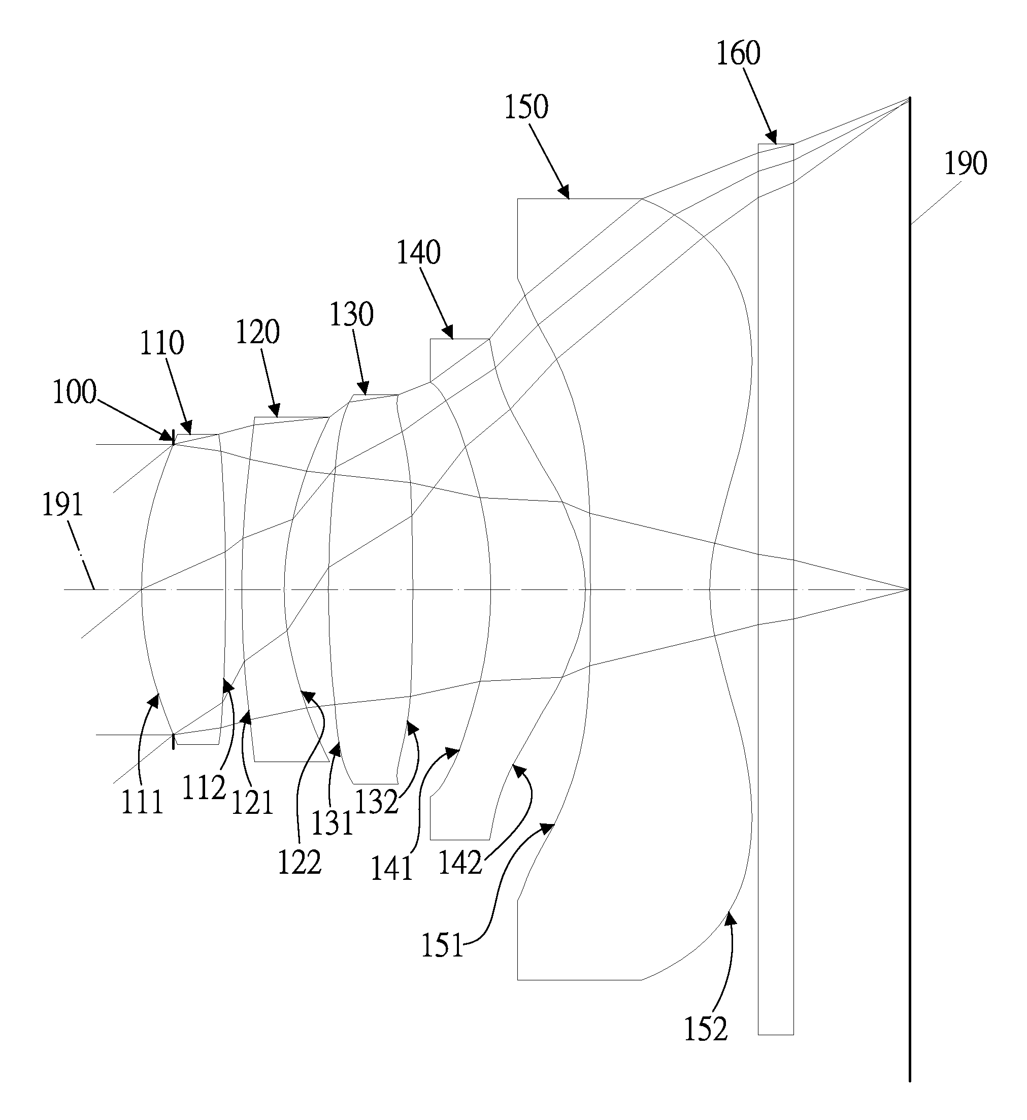
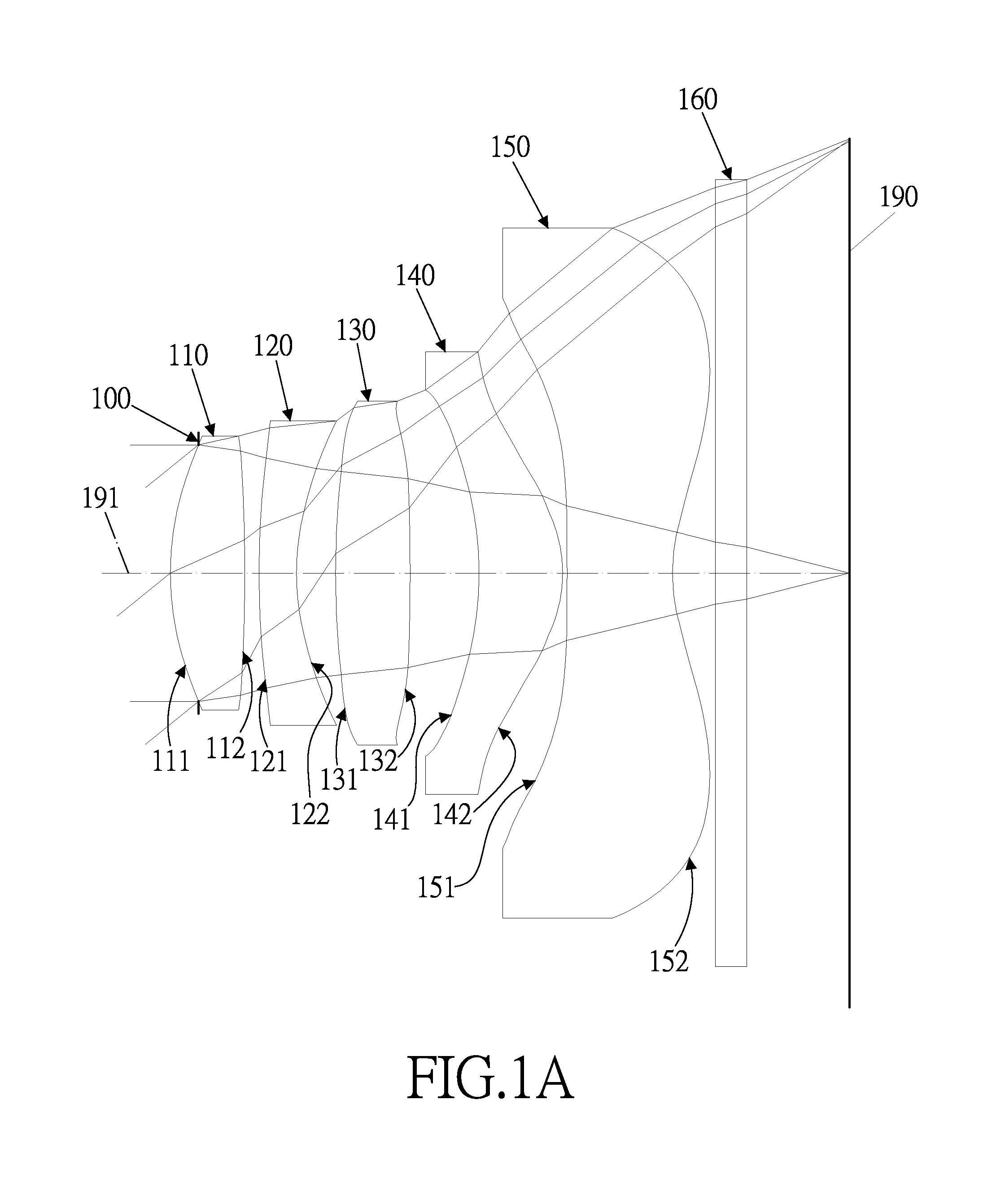
[0061]In the first embodiment of the present optical lens system, the focal length of the optical lens system is f, the f-number of the optical lens system is Fno, half of the maximum angle of field of view of the present optical lens system is HFOV, the maximum angle of field of view of the present optical ...

second embodiment

[0084]The equation for the aspheric surface profiles of the second embodiment is expressed as follows:

[0085]z⁡(h)=ch21+1-(1+k)⁢c2⁢h2+A4⁢h4+A6⁢h6+A8⁢h8+A10⁢h10+A12⁢h12+A14⁢h14+⁢⋯

[0086]z represents the distance of a point on the aspheric surface at a height h from the optical axis relative to a plane perpendicular to the optical axis at the vertex of the aspheric surface;

[0087]c is a paraxial curvature equal to 1 / R (R: a paraxial radius of curvature);

[0088]h represents a vertical distance from the point on the curve of the aspheric surface to the optical axis;

[0089]k represents the conic constant;[0090]A4, A6, Ag, A10, A12, A14 . . . : represent the high-order aspheric coefficients.

[0091]In the second embodiment of the present optical lens system, the focal length of the optical lens system is f, the f-number of the optical lens system is Fno, half of the maximum angle of field of view of the present optical lens system is HFOV, the maximum angle of field of view of the present optica...

third embodiment

[0114]The equation for the aspheric surface profiles of the third embodiment is expressed as follows:

[0115]z⁡(h)=ch21+1-(1+k)⁢c2⁢h2+A4⁢h4+A6⁢h6+A8⁢h8+A10⁢h10+A12⁢h12+A14⁢h14+⁢⋯

[0116]z represents the distance of a point on the aspheric surface at a height h from the optical axis relative to a plane perpendicular to the optical axis at the vertex of the aspheric surface;

[0117]c is a paraxial curvature equal to 1 / R (R: a paraxial radius of curvature);

[0118]h represents a vertical distance from the point on the curve of the aspheric surface to the optical axis;

[0119]k represents the conic constant;[0120]A4, A6, Ag, A10, A12, A14 . . . : represent the high-order aspheric coefficients.

[0121]In the third embodiment of the present optical lens system, the focal length of the optical lens system is f, the f-number of the optical lens system is Fno, half of the maximum angle of field of view of the present optical lens system is HFOV, the maximum angle of field of view of the present optical ...


PUM


Abstract

An optical lens system having a small F number, a wide angle of view, a short total length and a low manufacturing cost, includes, in order from an object side to an image side: a stop; a first lens element with a positive refractive power; a meniscus second lens element with a negative refractive power; a third lens element with a positive refractive power; a fourth lens element with a positive refractive power; a fifth lens element with a negative refractive power, the optical lens system has a focal length of f, the first lens element has a focal length f1, the third lens element has a focal length f3, the fourth lens element has a focal length f4, the fifth lens element has a focal length f5, and they satisfy the conditions: 0.4<f4 / f<1.0; −0.8<f5 / f<−0.4; and f1 / f<1.2<f3 / f.

Description

BACKGROUND OF THE INVENTION[0001]1. Field of the Invention[0002]The present invention relates to an optical lens system, and more particularly to a five-piece optical lens system applicable to electronic products.[0003]2. Description of the Prior Art[0004]With the consumer electronic industry continuously growing, the current market demand for small imaging lens system is also increasing. Especially for the imaging lens application in mobile phone, tablet computer and notebook, optical lens system has almost become mainstream in the market. Optical lens has been developed into multiple-piece lens system from the early two-piece lens system, in order to enhance resolution and image quality. Moreover, as electronic products are becoming thinner, lighter and easier to carry, the imaging lens system also needs to be further reduced in size in order to fit in the increasingly miniaturized carrier, meanwhile, it would be better to have a smaller F number, so that the imaging lens system i...

Claims


Application Information

Patent Timeline
Patent Type & Authority Patents(United States)
IPC IPC(8): G02B3/02G02B13/18
CPCG02B13/18G02B13/0045
Inventor CHUNG, FENG-CHAOCHANG, SHIH-YUANLIU, KUN-TI
Owner GLORY SCI
Why Eureka
Try Eureka