
Method for sorting CT image slices and method for constructing 3D CT image

a ct image and slice technology, applied in the field of computerized tomography, can solve the problems of limited total ct slice number and storage ability, significant distortion of target contouring of tumors, and too dense sampling ra

Active Publication Date: 2014-10-28
GE HANGWEI MEDICAL SYST
View PDF19 Cites 2 Cited by
  • Summary
  • Abstract
  • Description
  • Claims
  • Application Information

AI Technical Summary

Benefits of technology

The present invention provides methods to improve the quality of 3D CT images in 4D CT to overcome the issues caused by insufficient sampling rate. These methods can help to reduce or eliminate defects in the images and improve the overall accuracy and reliability of the imaging process.

Problems solved by technology

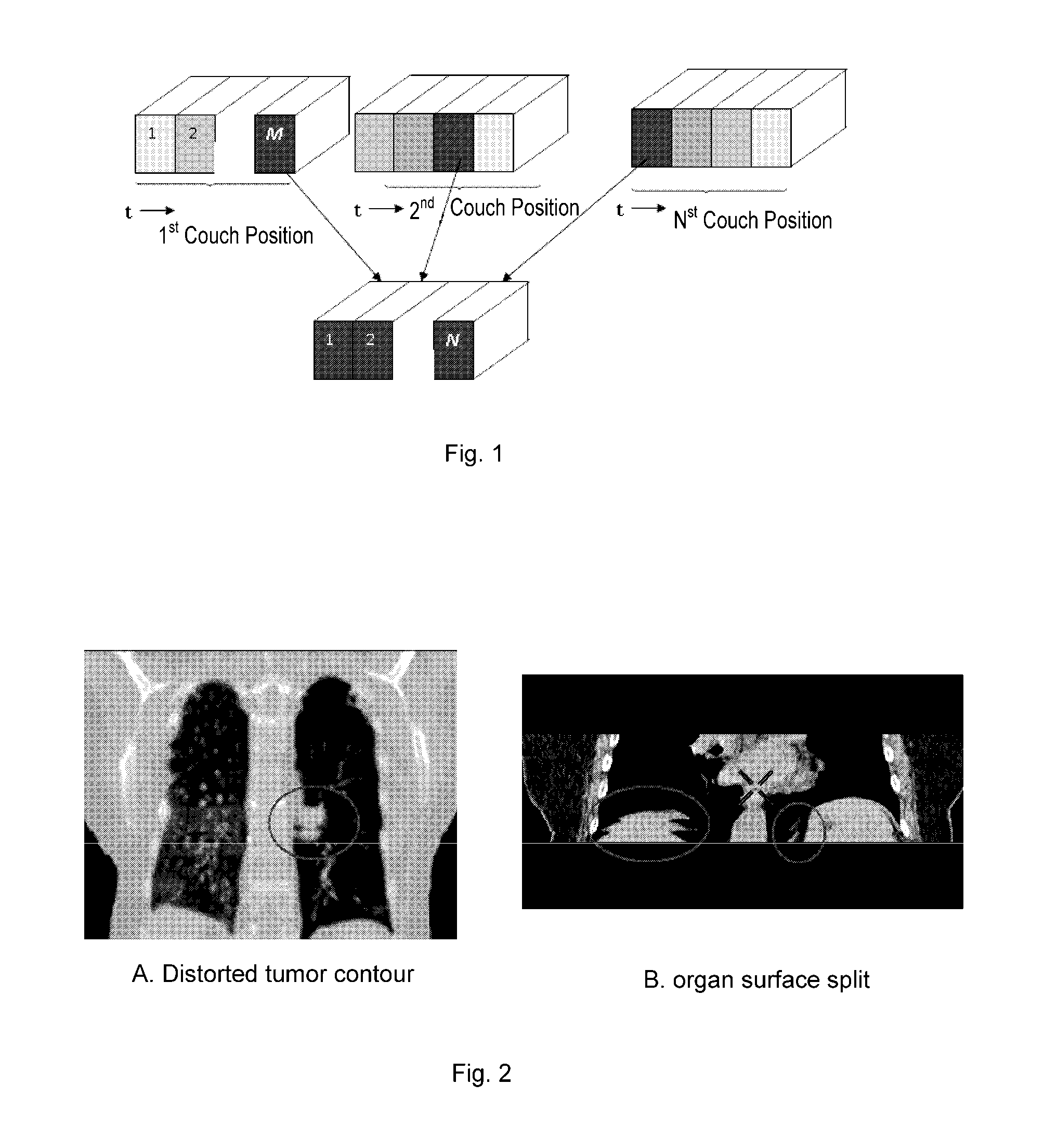
Patient's respiratory motion during free-breathing CT scan may cause significant distortions in target contouring of tumors in the 3D image of the thorax and the upper abdomen.
However, in most clinical 4D CT scans, there are always some reasons which prevent the sampling rate from being set too dense, such as the requirement for reducing X-ray dose to the patient, the limitation of the total CT slice number and the storage ability, or the requirement for improving scan and processing speed.
One is the insufficiency of sampling points in the whole breathing cycle.
Consequently, about 10% mismatches are caused by insufficient sampling rate.
The second aspect may cause even more serious mismatch.
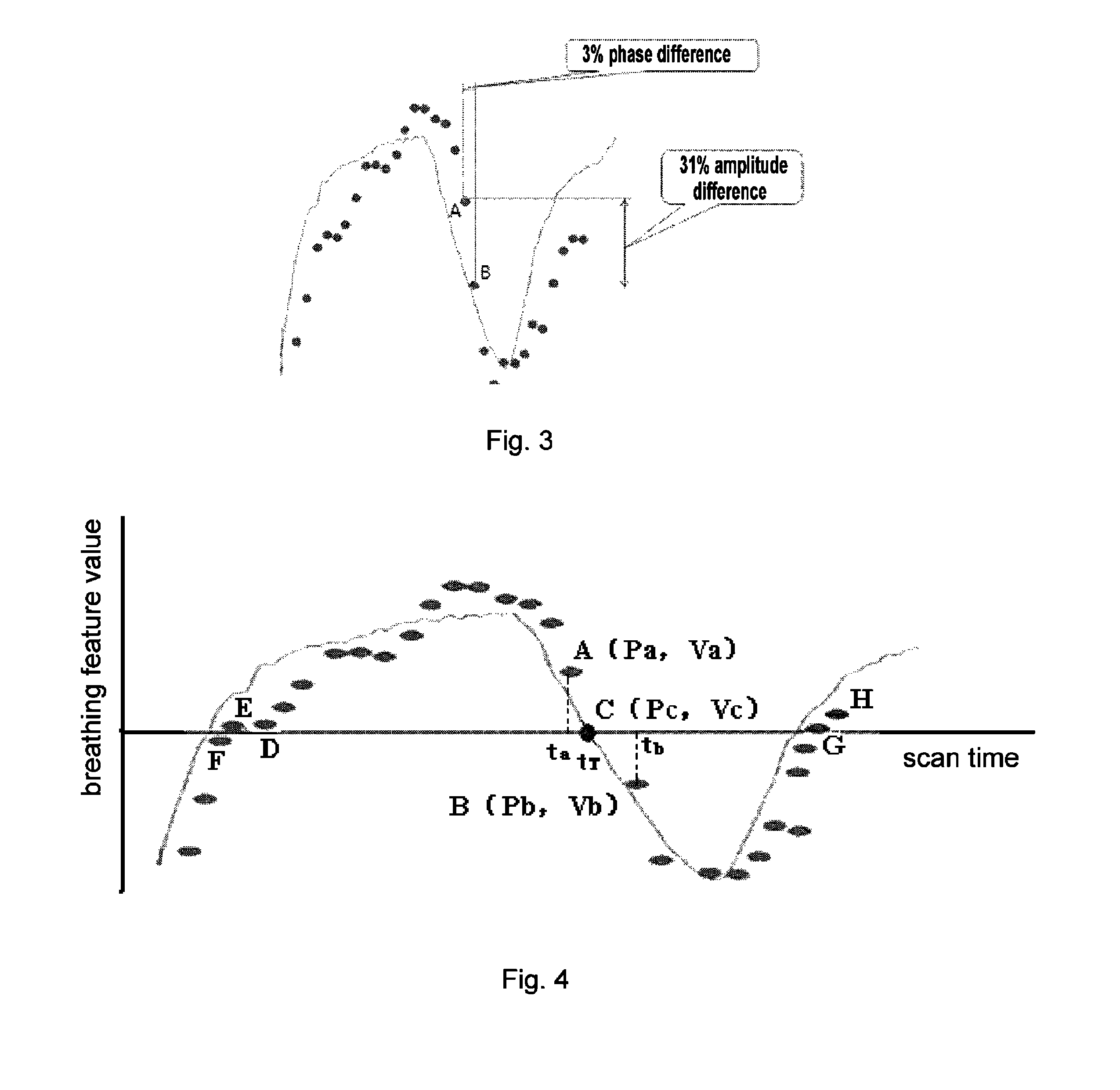
As can be seen from FIG. 3, the breathing feature values change dramatically in the middle of the expiration phase (as shown by the red circle), and sampling rate is especially insufficient for these parts.
By checking the 3D CT images, it is discovered that 3D mismatch mainly occurs in these situations.
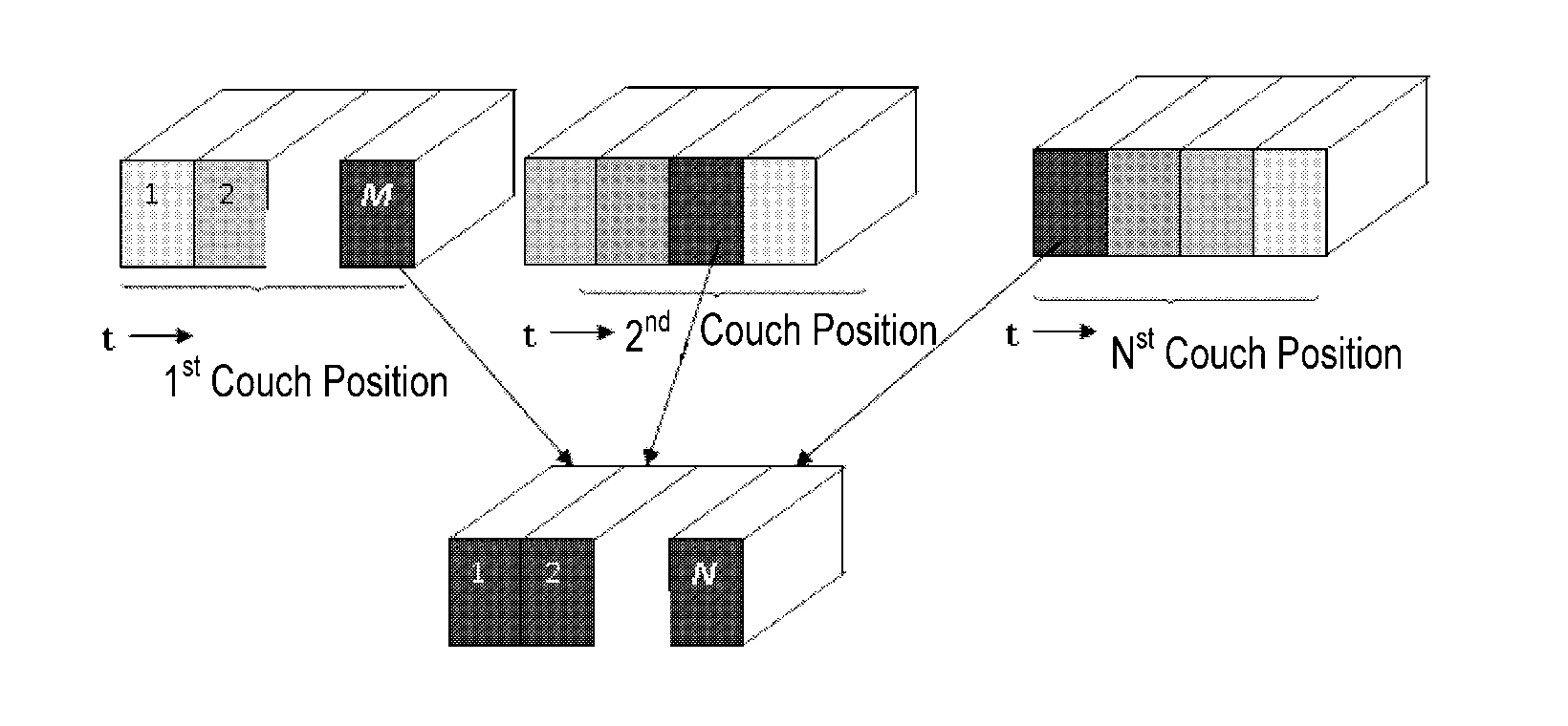
Therefore, for two adjacent couch (Z) CT slices, when they are stacked to a 3D image, if there is a small phase shift between the two samples, then the two images chosen may have obviously different appearance, thereby causing an obvious mismatch along the Z direction in the resulting 3D image.

Method used


Image

  • Method for sorting CT image slices and method for constructing 3D CT image
  • Method for sorting CT image slices and method for constructing 3D CT image
  • Method for sorting CT image slices and method for constructing 3D CT image

Examples


Embodiment Construction

[0020]Embodiments of the present invention relate to a method of automatic compensation for the sorting result in low sampling rate 4D CT. According to embodiments of the present invention, a Virtual Interpolated Compensation technology successfully improves 4D CT sorting result performance by compensating the defects caused by sparse sampling. The technology according to embodiments of the present invention effectively address the issues noted in the above-mentioned second aspect about the impacts caused by low sampling rate.

[0021]The following is a detailed description of the specific embodiments of the present invention. However, it will be appreciated that the present invention is not limited to said specific embodiments.

[0022]FIG. 4 schematically illustrates a circumstance where the image slice sorting method according to an embodiment of the present invention is to be applied. In FIG. 4, the elliptic points represent the corresponding breathing data extracted from each image s...


PUM


Abstract

A method for sorting CT image slices comprising, if no image slice comprises a target respiratory phase at a couch position, determining a target breathing feature value corresponding to the target respiratory phase based on a respiratory motion curve of a scanned patient, searching from a plurality of image slices at the couch position for one or more image slices comprising a breathing feature value close to the target breathing feature value to serve as candidate image slices, and selecting, based on a breathing feature value difference between the breathing feature value of each of the candidate image slices and the target breathing feature value and / or an image difference between each of the candidate image slices and at least one reference image slice, a single image slice from the candidate image slices for constructing the 3D CT image for the target respiratory phase.

Description

BACKGROUND OF THE INVENTION[0001]1. Field of the Invention[0002]Embodiments of the present invention relate to the field of computerized tomography (CT) and, more particularly, to a method for sorting CT image slices and a method for constructing a 3-dimensional (3D) CT image using the sorted CT image slices.[0003]2. Description of the Prior Art[0004]Patient's respiratory motion during free-breathing CT scan may cause significant distortions in target contouring of tumors in the 3D image of the thorax and the upper abdomen. In order to eliminate or reduce the effect caused by respiratory motion generated artifacts on the CT scan of the chest and abdomen of the patient, achieving the purpose of accurate diagnosis and treatment, the concept of four-dimensional (4D) CT has been proposed. The 4D CT technique has been widely used for treatment simulation of thoracic and abdominal cancer radiotherapy. 4D CT can be accomplished by over-sampling CT slices at each couch (Z direction) positio...

Claims


Application Information

Patent Timeline
Patent Type & Authority Patents(United States)
IPC IPC(8): G06K9/00G06T11/00
CPCG06T2211/412G06T11/005G06K9/00
Inventor LIU, PINGDONG, JIAQINWANG, SHUANG
Owner GE HANGWEI MEDICAL SYST
Learn More