Circular filtering disc and filter device having the same

a filter disc and disc technology, applied in the direction of moving filter element filters, filtration separation, separation processes, etc., can solve the problems of reducing the filtering efficiency and increasing the maintenance cost of the filter device, and achieve the effect of improving the filtering efficiency, water pressure, and preventing the filter disc from breaking

Active Publication Date: 2014-11-04
K 1 ECOTECH
View PDF5 Cites 2 Cited by
  • Summary
  • Abstract
  • Description
  • Claims
  • Application Information

AI Technical Summary

Benefits of technology

[0015]Accordingly, the present invention has been made keeping in mind the above problems occurring in the related art, and the present invention is intended to propose a circular filtering disc and a filter device having the filtering disc, in which raw water can flow into the filter device through the circumferential edges of a plurality of filtering discs stacked on top of one another in the filter device and filtered pure water can be collected in the center of the filtering discs and is discharged from the filter device through the center, so that water pressure can be evenly distributed over the entire surface of filtering discs and thereby the filtering discs can be protected from breaking.
[0016]Further, the present invention is intended to provide a circular filtering disc and a filter device having the filtering disc, which has improved filtering efficiency and in which a filter fabric can be evenly spread out over the entire surface of the fabric.
[0021]In the circular filtering disc and the filter device having the filtering disc according to the present invention, raw water to be filtered can be evenly supplied to the filtering disc through a plurality of vertical inlet holes formed through the circumferential edge of the filtering disc at locations over the entire circumferential edge and filtered pure water can be discharged from the filtering disc through a vertical outlet hole formed through the center of the filtering disc, so that the present invention realizes improved filtering efficiency.
[0022]Further, the raw water to be filtered can be evenly supplied to the filtering disc through the vertical inlet holes formed through the circumferential edge of the filtering disc at locations over the entire circumferential edge, so that the water pressure acting on the filter device can be reduced and the device is not loaded with excessive water pressure, thus preventing the filtering discs from breaking.
[0023]Further, the raw water to be filtered can be evenly supplied to the filter fabric by way of the vertical inlet holes formed through the circumferential edge of the filtering disc at locations over the entire circumferential edge, so that the raw water can be evenly filtered by the entire surface of the filter fabric. Therefore, contaminants can be evenly distributed over the entire surface of the filter fabric, so that the frequency of back-flushing or changing the filter fabrics can be minimized, thus reducing the maintenance expenses of the filter device.

Problems solved by technology

Therefore, water resistance acting on the filtering disc is not evenly distributed on the entire surface of the filtering disc, but is concentrically distributed on the left and right edges of the filtering disc, thus reducing the filtering efficiency.
Further, because water pressure concentrically acts on the edges of the filtering disc, when the filtering disc receives an impact at the edges it may break.
Further, the filter fabrics are partially contaminated at the edges, so that the filtering discs must be frequently replaced by new ones, thus increasing the maintenance cost of the filter device.

Method used


Image

  • Circular filtering disc and filter device having the same
  • Circular filtering disc and filter device having the same
  • Circular filtering disc and filter device having the same

Examples


Embodiment Construction

[0030]Reference will now be made in greater detail to a preferred embodiment of the invention, an example of which is illustrated in the accompanying drawings. Wherever possible, the same reference numerals will be used throughout the drawings and the description to refer to the same or like parts.

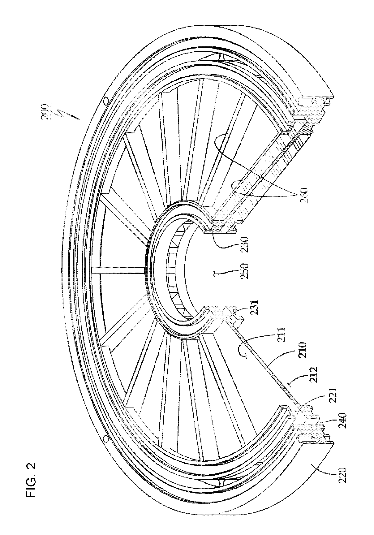
[0031]FIGS. 2 through 5 are views illustrating a filter device having filtering discs according to the present invention.

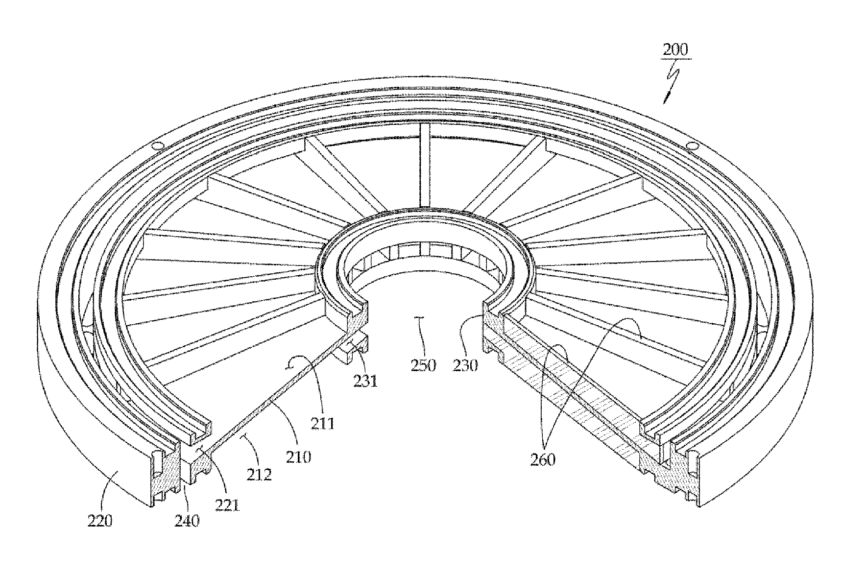
[0032]As shown in FIG. 2, the circular filtering disc 200 according to the present invention comprises a circular inner hub 230 and a circular outer rim 220, which has a diameter larger than that of the inner hub 230 and surrounds the inner hub 230. A partition plate 210 radially extends between the outer rim 220 and the inner hub 230 and separates the upper space from the lower space. The partition plate 210 is preferably inclined such that the height of the inner hub 230 is higher or lower that of the outer rim 220.

[0033]Therefore, an upper channel 211 and a lower chan...


PUM

PropertyMeasurementUnit
heightaaaaaaaaaa
shapeaaaaaaaaaa
thicknessaaaaaaaaaa

Abstract

A circular filtering disc and a filter device having the filtering disc. The filtering disc includes a circular partition plate having an inner hub and an outer rim, with radial inlet holes formed in the outer rim and introducing water to the partition plate, and a vertical outlet hole formed in the center of the inner hub and discharging pure water; and a filter fabric placed on or below the partition plate, wherein water supplied to the filtering disc passes through the filter fabric and becomes concentrated at the vertical outlet hole, and is discharged from the filtering disc through the vertical outlet hole. In the filter device, raw water is supplied through the circumferential edges of the circular filtering discs stacked on top of one another in the filter device and is filtered prior to being discharged from the filter device through the center of the filtering discs.

Description

CROSS REFERENCE[0001]This application claims foreign priority under Paris Convention and 35 U.S.C. §119 to Korean Patent Application No. 10-2010-0035619, filed Apr. 19, 2010 with the Korean Intellectual Property Office.BACKGROUND OF THE INVENTION[0002]1. Technical Field[0003]The present invention relates, in general, to a circular filtering disc and a filter device having the filtering disc and, more particularly, to a circular filtering disc and a filter device having the filtering disc, in which raw water is supplied to the filter device through the circumferential edges of a plurality of circular filtering discs stacked on top of one another in the filter device and is filtered prior to being discharged from the filter device through the center of the filtering discs.[0004]2. Description of the Related Art[0005]Generally, to produce drinking water from the raw water of a natural spring, the raw water must be subjected to several processes for removing sludge from the water and fo...

Claims


Application Information

Patent Timeline
Patent Type & Authority Patents(United States)
IPC IPC(8): B01D29/00B01D25/26B01D29/39
CPCB01D25/26
Inventor CHOI, CHANG HYUNNO, DAE HYUNKIM, JONG SANG
Owner K 1 ECOTECH
Why Eureka
Try Eureka