Pressure limiter

a technology of pressure limiter and compressor housing, which is applied in the direction of pump control, packaging, pump components, etc., can solve the problems of releasing excess pressure either upward or downward, the pressure release device cannot be bypassed by the user, and the pressure release device cannot be closed and replaced, so as to prevent the expansion and contraction of the compressor housing from impairing the function of the pressure release device, and the pressure is evenly distributed.

Inactive Publication Date: 2008-07-24
TECUMSEH PROD CO
View PDF16 Cites 3 Cited by
  • Summary
  • Abstract
  • Description
  • Claims
  • Application Information

AI Technical Summary

Benefits of technology

[0007]Advantageously, the present pressure release device provides for the release of fluid at a predetermined pressure irrespective of the thickness of the compressor housing. Thus, the pressure release device can be used interchangeably with compressors having varying housing thicknesses. This eliminates the need to modify the size or shape of the pressure release device for different compressor housings. Additionally, the flange of the pressure release device is positioned adjacent the interior of the compressor housing, which, due to the pressure within the housing, forces the flange against the inner surface of the housing. In the event the rupture portion of the pressure release device opens, the interaction between the flange of the pressure release device and the inner surface of the housing secures the pressure release device to the housing. Moreover, by positioning the pressure release device over and / or in an aperture in the compressor housing, the pressure release device cannot be bypassed by the user. Thus, once the rupture portion of the pressure release device has opened, allowing the release of fluid from the compressor housing, the pressure release device cannot be closed and the compressor housing must be replaced.
[0008]In one exemplary embodiment, the present pressure release device is positioned on a sidewall of the compressor housing opposite the electric terminal cluster. Advantageously, this allows the excess pressure to be released to a single side of the compressor typically away from someone servicing the compressor. In contrast, prior art devices would often release excess pressure either upward or downward. When released upward, the excess pressure would force working fluid upward, toward any person standing at or near the compressor. Alternatively, when released downward, the excess pressure would force working fluid into a support or base upon which the compressor was mounted, causing the working fluid to be deflected in any or all directions. Additionally, in another exemplary embodiment, the pressure release device is configured to be attached to a flattened portion of the compressor housing. This allows the pressure release device to evenly distribute pressure encountered during operation of the compressor and prevents expansion and contraction of the compressor housing from impairing the function of the pressure release device.

Problems solved by technology

Moreover, by positioning the pressure release device over and / or in an aperture in the compressor housing, the pressure release device cannot be bypassed by the user.
Thus, once the rupture portion of the pressure release device has opened, allowing the release of fluid from the compressor housing, the pressure release device cannot be closed and the compressor housing must be replaced.
In contrast, prior art devices would often release excess pressure either upward or downward.

Method used


Image

  • Pressure limiter
  • Pressure limiter
  • Pressure limiter

Examples


Embodiment Construction

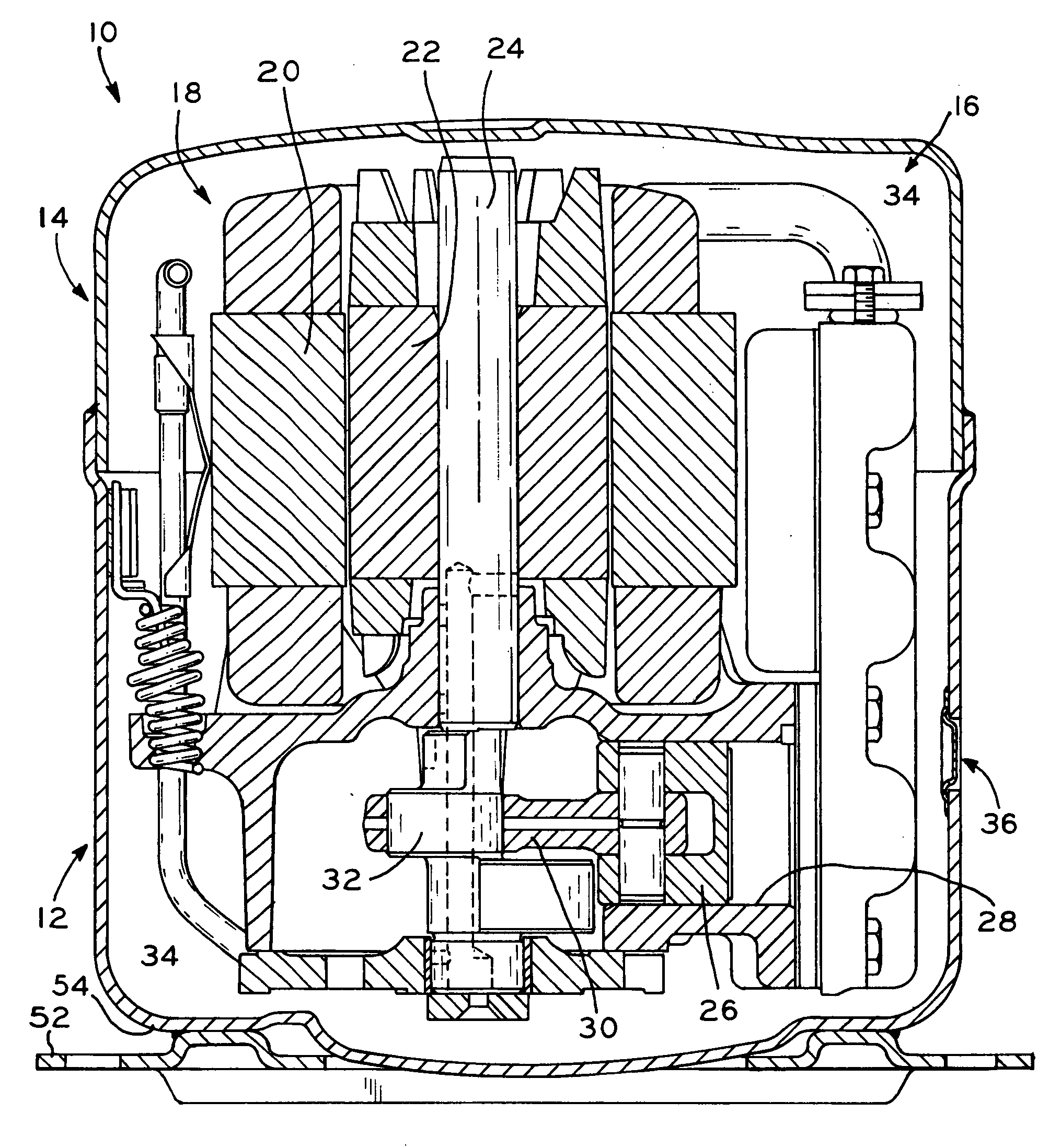
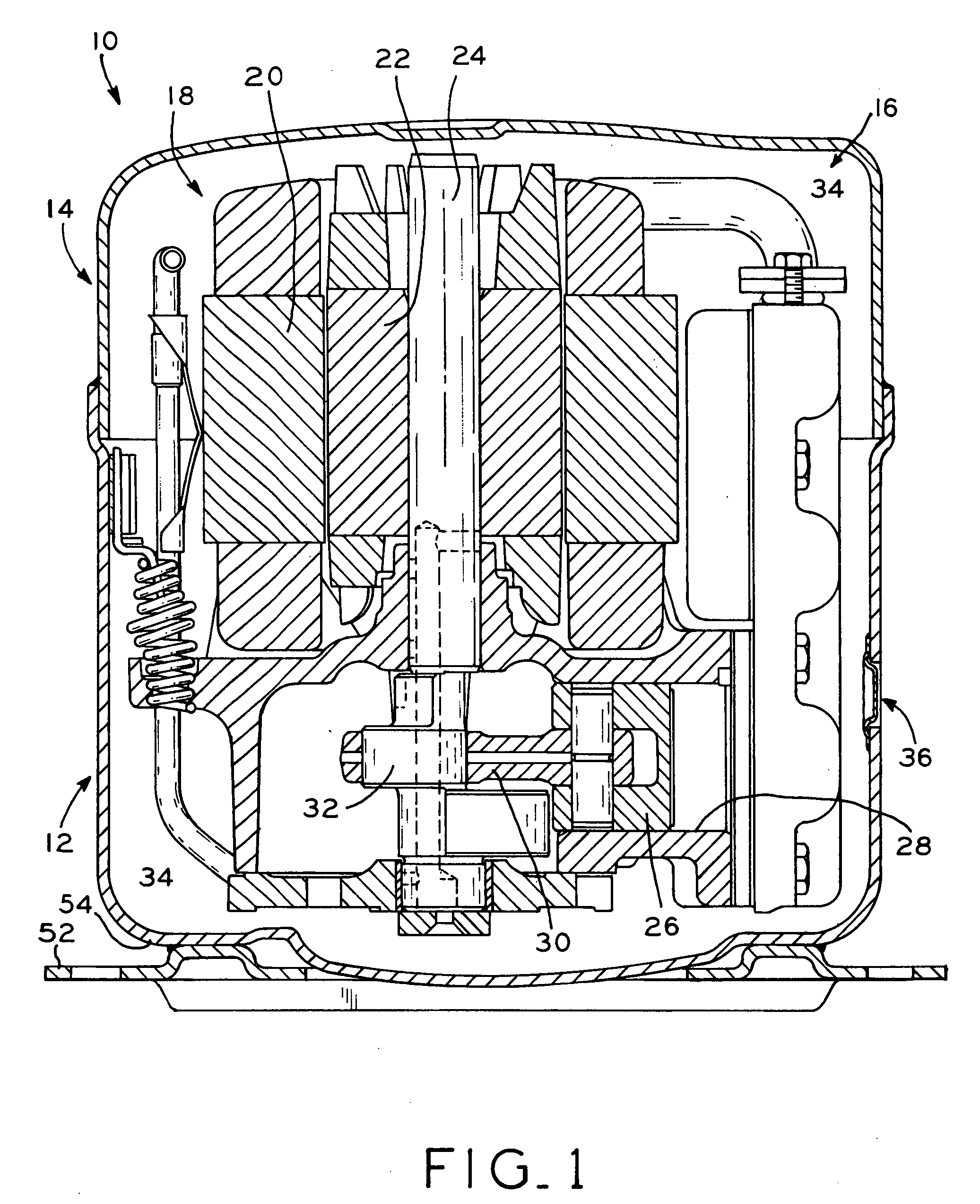
[0022]Referring to FIG. 1, hermetically sealed compressor housing 10 includes lower housing portion 12 and upper housing portion 14. Compressor mechanism 16 is positioned within compressor housing 10 and includes motor 18 having stator 20 and rotor 22, which drive crankshaft 24 in a known manner. Compressor mechanism 16 is depicted as a radial piston compressor having piston 26 positioned within cylinder 28. Piston 26 reciprocates within cylinder 28 via connecting rod 30 and eccentric 32 in a known manner. While compressor mechanism 16 is depicted and described herein as a radial piston compressor, any known compressor mechanism, e.g., a scroll or rotary compressor, may be utilized. When compressor mechanism 16 is in operation, fluid is compressed from a low, suction pressure to a higher, discharge pressure. The fluid is then discharged into plenum 34 of compressor housing 10, increasing the pressure therein until it reaches the discharge pressure. In the event of a compressor malfu...


PUM


Abstract

A hermetically sealed compressor including a pressure release device. In one exemplary embodiment, the pressure release device includes a flange portion and a rupture portion. The flange portion is positioned against and secured to the inner surface of the housing of a hermetically sealed compressor. In this embodiment, the rupture portion extends at least partially within a vent aperture extending through the compressor housing. When the interior pressure of the housing exceeds a predetermined limit, the rupture portion of the pressure release device opens allowing the fluid within the compressor housing to escape. In another exemplary embodiment, the pressure release device further includes a connecting portion positioned between the flange portion and the rupture portion. In one exemplary embodiment, the connecting portion forms an S-curve.

Description

BACKGROUND[0001]1. Field of the Invention.[0002]The present invention relates to a pressure release device, particularly to a pressure release device for use with hermetically sealed compressors.[0003]2. Description of the Related Art.[0004]During operation of a hermetically sealed compressor, fluid, such as refrigerant, is compressed by a compressor mechanism positioned within a housing. In a “high side” compressor, the fluid is discharged into the housing, increasing the pressure therein to equal the discharge pressure of the fluid. To ensure effective operation of the compressor in adverse conditions, the housing of a hermetically sealed compressor is designed to withstand internal pressures substantially greater than the discharge pressure of the fluid. However, when a fan is blocked or when a substance having a lower boiling point than the fluid, such as water, is introduced into the system, the pressure within the housing may rise to a pressure exceeding the upper pressure lim...

Claims


Application Information

Patent Timeline
Patent Type & Authority Applications(United States)
IPC IPC(8): B65D90/32
CPCF04B49/10F04B39/121
Inventor TOMELL, PHILLIP A.
Owner TECUMSEH PROD CO
Why Eureka
Try Eureka