Midfoot orthotic shoe insert

a technology for orthotics and shoes, applied in the field of midfoot orthotic shoe inserts, can solve the problems of abnormalities and injuries of the foot, excessive stress and strain of the feet, and insufficient comfort, so as to reduce pressure, improve comfort, and reduce stress

Active Publication Date: 2019-05-28
GOSSMAN LAINA
View PDF6 Cites 3 Cited by
  • Summary
  • Abstract
  • Description
  • Claims
  • Application Information

AI Technical Summary

Benefits of technology

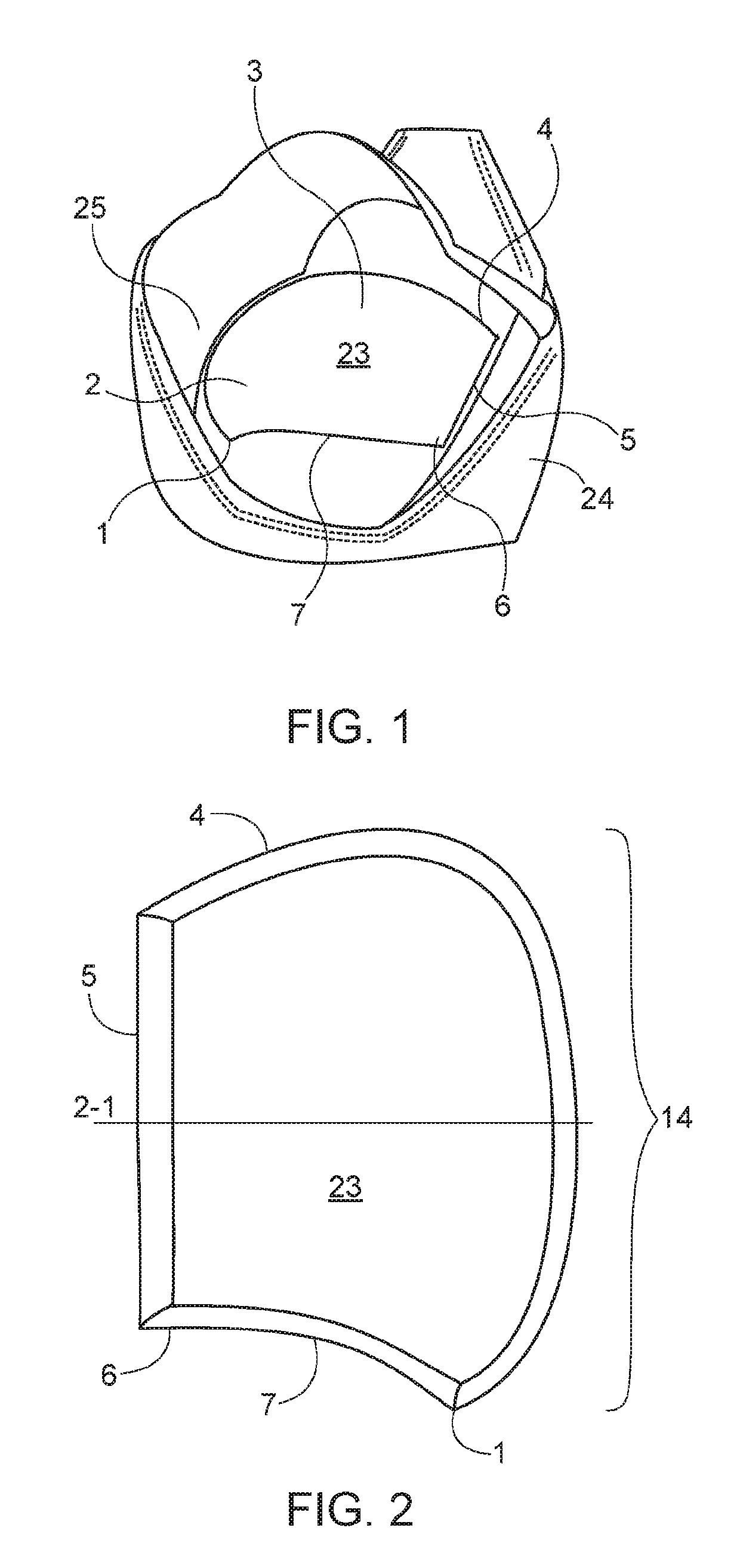
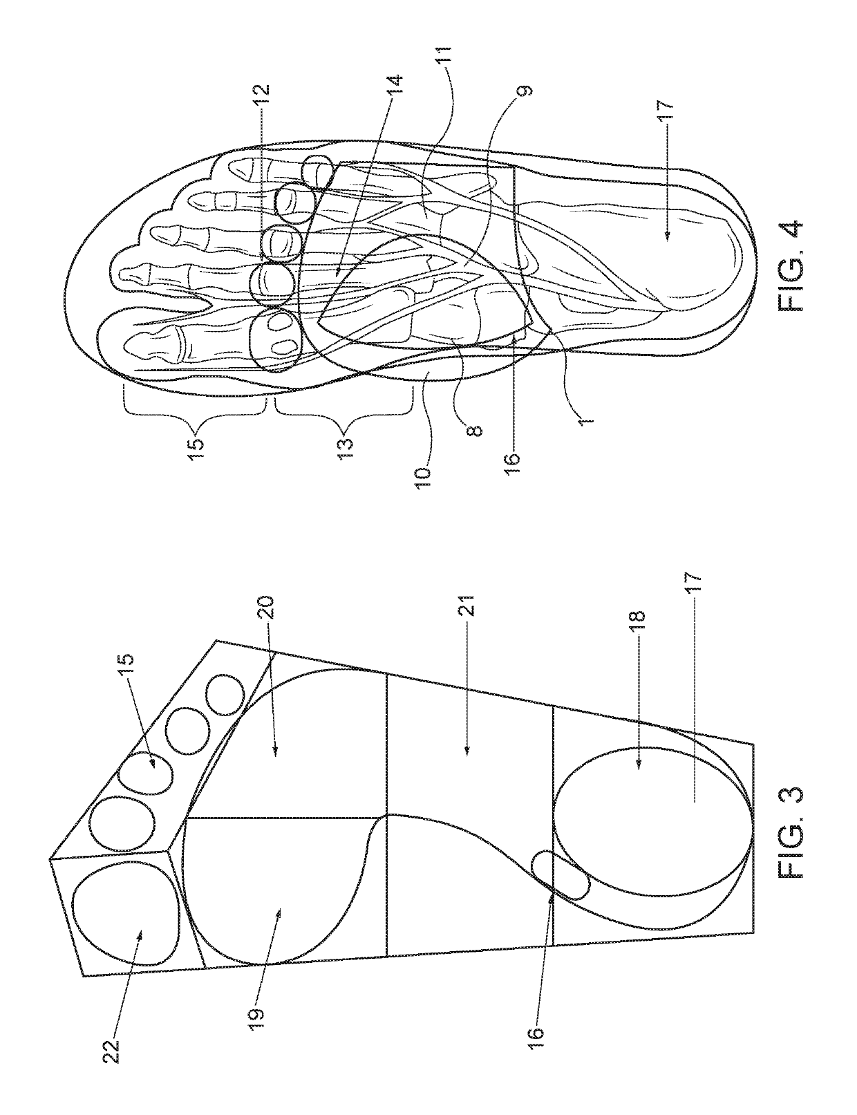
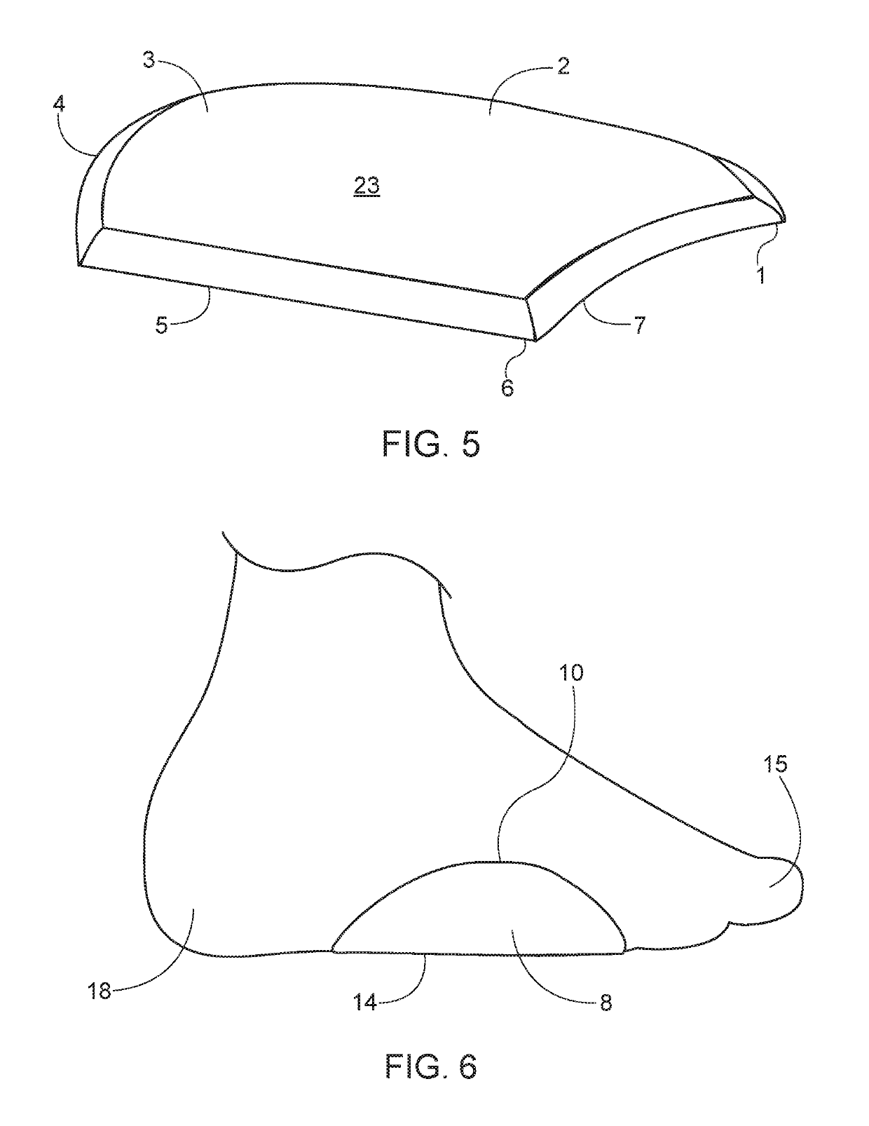
[0007]The present disclosure provides a new approach to orthotic shoe inserts. The disclosed device is uniquely designed to sit in the midfoot region of an article of footwear to relieve pressure from the heel and forefoot, redistribute pressure more evenly across the foot, support the foot arches, improve comfort, correct abnormalities, and prevent foot problems or injury occurring while wearing shoes. This present invention is made from a flexible material and has a unique shape that does not crowd shoes, forms to the shape of any shoe and does not cause heel slip.

Problems solved by technology

Without proper alignment of the joints of the feet, excessive stress and strain can occur in the feet as well as elsewhere in the body.
The human foot may be subject to a variety of abnormalities that cause pain.
Abnormalities and injuries of the foot may be caused by or made worse by footwear which does not properly support the foot.
While there has been substantial investigation by prior art workers into orthotic devices, there has been little success designing functional orthotics for reducing injury or increasing comfort of slim-fitting shoes, high heeled shoes, shoes without removable insoles, and sandals.
While the design of these shoes vary, it is generally common for these fashion shoes to leave no space for the conventional orthotic, and these shoes generally do not have a removable insole that can be replaced with a conventional orthotic.
Sandals are another example of footwear in which prior designs and conventional orthotics will not fit.
These conventional and prior orthotic designs will crowd the sandal, visibly distract from the original appearance, and will not stay securely in place.

Method used


Image

  • Midfoot orthotic shoe insert
  • Midfoot orthotic shoe insert
  • Midfoot orthotic shoe insert

Examples


Embodiment Construction

[0020]In the following description, numerous specific details are set forth in order to provide a thorough understanding of the present invention. It will be apparent, however, to one having ordinary skill in the art that the specific detail need not be employed to practice the present invention. In other instances, well-known materials or methods have not been described in detail in order to avoid obscuring the present invention.

[0021]Reference throughout this specification to “one embodiment”, “an embodiment”, “one example” or “an example” means that a particular feature, structure or characteristic described in connection with the embodiment or example is included in at least one embodiment of the present invention. Thus, appearances of the phrases “in one embodiment”, “in an embodiment”, “one example” or “an example” in various places throughout this specification are not necessarily all referring to the same embodiment or example. Furthermore, the particular features, structure...


PUM

PropertyMeasurementUnit
thicknessaaaaaaaaaa
thicknessaaaaaaaaaa
thicknessaaaaaaaaaa

Abstract

The present invention relates generally to a device for supporting the foot and more particularly to a device for relieving pressure from specific areas of the foot, and for relaxing and shortening the musculatures of the foot by raising the arch. Through specific shapes and materials, the design intends to aid in alignment, add comfort, and prevent and relieve many foot problems and other lower extremity ailments. The device is uniquely designed to sit in the midfoot region of an article of footwear to relieve pressure from the heel and forefoot, redistribute pressure more evenly across the foot, and support the foot arches. The device may be constructed from flexible material which allows the orthotic to form to the shape of the shoe it is placed in. The medial wing portion of the orthotic device may utilize the medial wall of a shoe to increase arch support.

Description

RELATED APPLICATIONS[0001]The present application claims the benefit of U.S. Provisional Application Ser. No. 62 / 264,085, filed Dec. 7, 2015, which is expressly incorporated herein by reference in its entirety.BACKGROUND[0002]Feet are the foundation of the body. Without proper alignment of the joints of the feet, excessive stress and strain can occur in the feet as well as elsewhere in the body. The human foot may be subject to a variety of abnormalities that cause pain. Abnormalities and injuries of the foot may be caused by or made worse by footwear which does not properly support the foot.[0003]Constructions devised to correct abnormalities, aid in alignment, add comfort, and prevent foot problems or injury occurring while wearing shoes are generally referred to in the art as “orthotics”. Many orthotics are “full length” and intended to replace the existing insole within a shoe. It is also known in the prior art to provide orthotics comprising pads attached to the insole. These m...

Claims


Application Information

Patent Timeline
Patent Type & Authority Patents(United States)
IPC IPC(8): A43B7/14A43B17/14A43B17/02A43B17/00
CPCA43B7/149A43B7/142A43B17/14A43B17/026A43B17/003
Inventor GOSSMAN, LAINA
Owner GOSSMAN LAINA
Why Eureka
Try Eureka