
Bicycle frame for receiving a battery unit and associated battery unit

a battery unit and bicycle frame technology, applied in the field of bicycle frames, can solve the problems of reducing the free space otherwise available, affecting the cycling comfort of cyclists, and the bulky size of the battery container, and achieve the effect of reliable, safe and protected accommodation of the battery unit, and simple insertion and removal of the battery uni

Active Publication Date: 2014-11-11
THOMUS VELOSHOP
View PDF18 Cites 29 Cited by
  • Summary
  • Abstract
  • Description
  • Claims
  • Application Information

AI Technical Summary

Benefits of technology

[0004]It is therefore an object of the present invention to provide a bicycle frame of the kind mentioned in the introduction that allows a simple insertion and removal of a battery unit into and from the interior of the frame tube while avoiding the foregoing disadvantages, and that simultaneously ensures a reliable and safely protected accommodation of the battery.
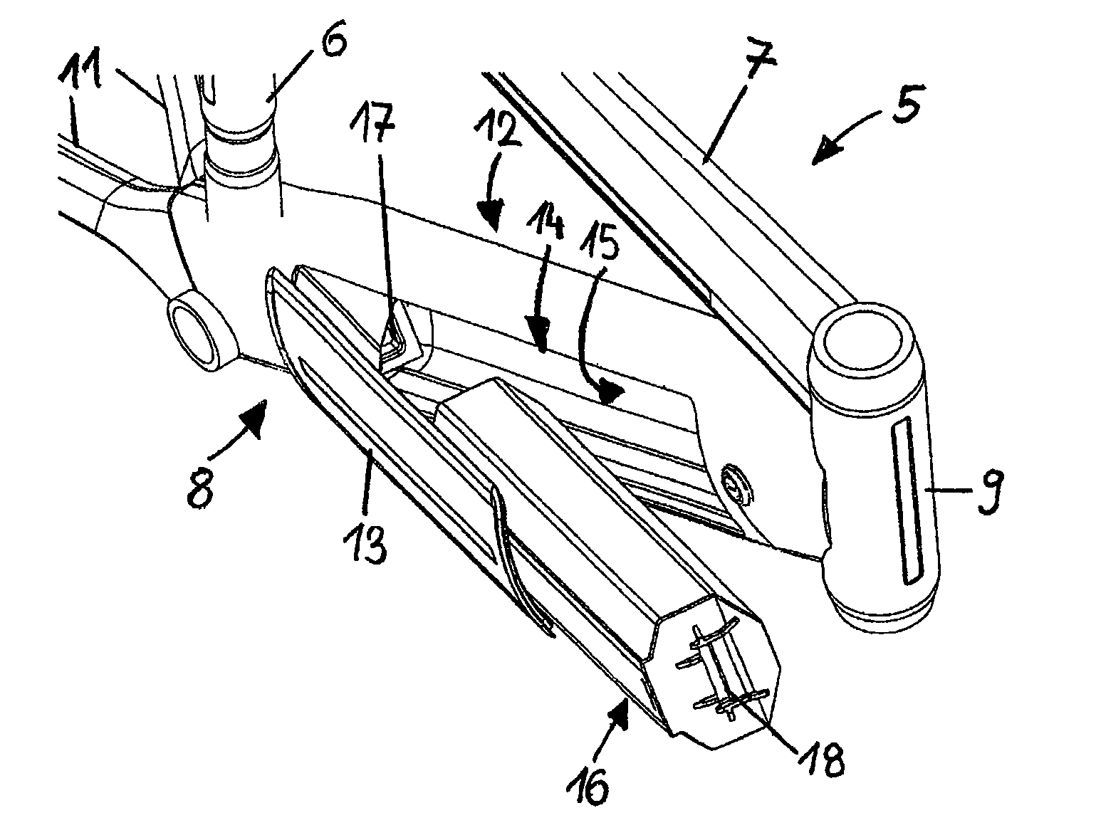
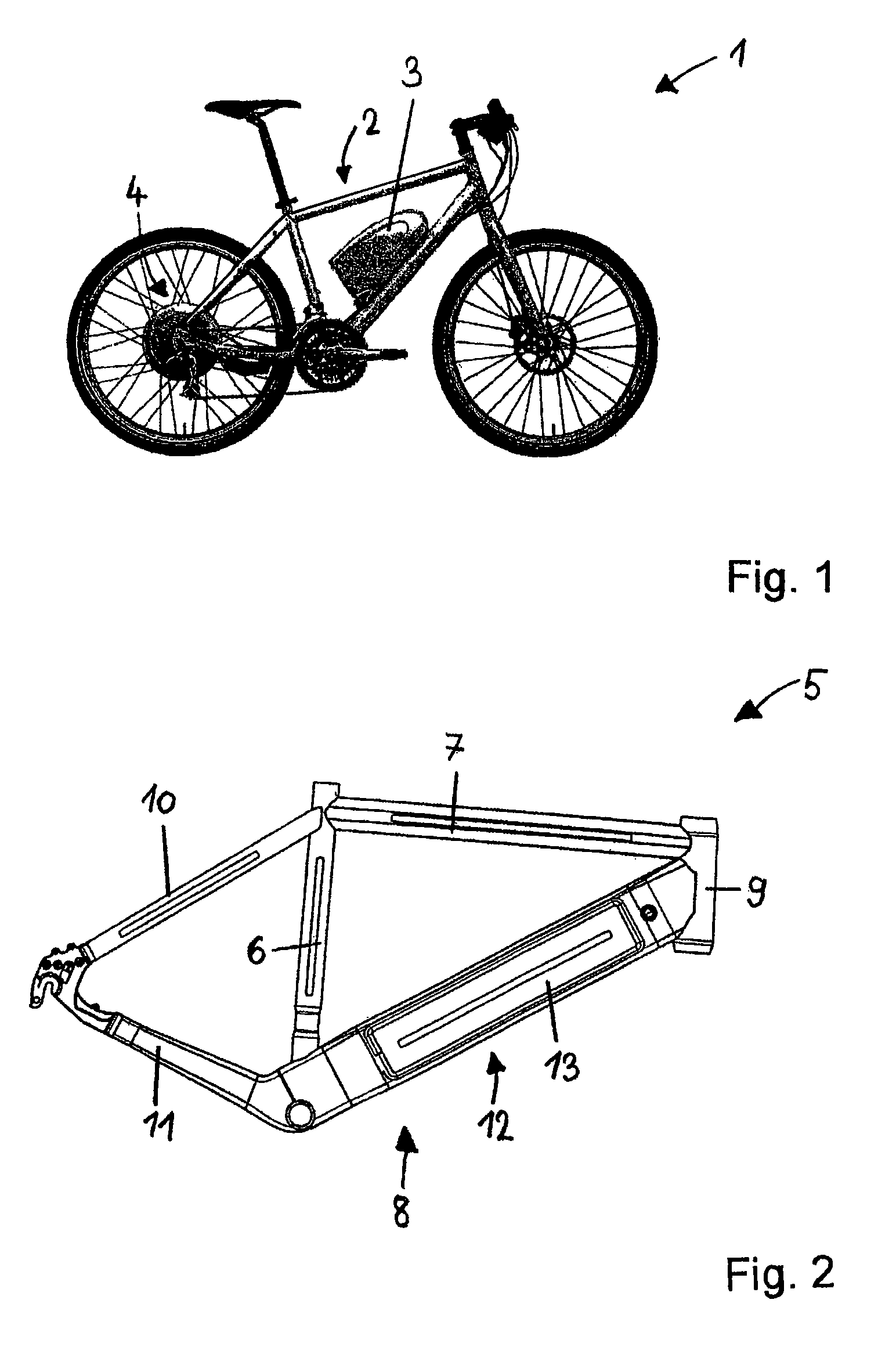
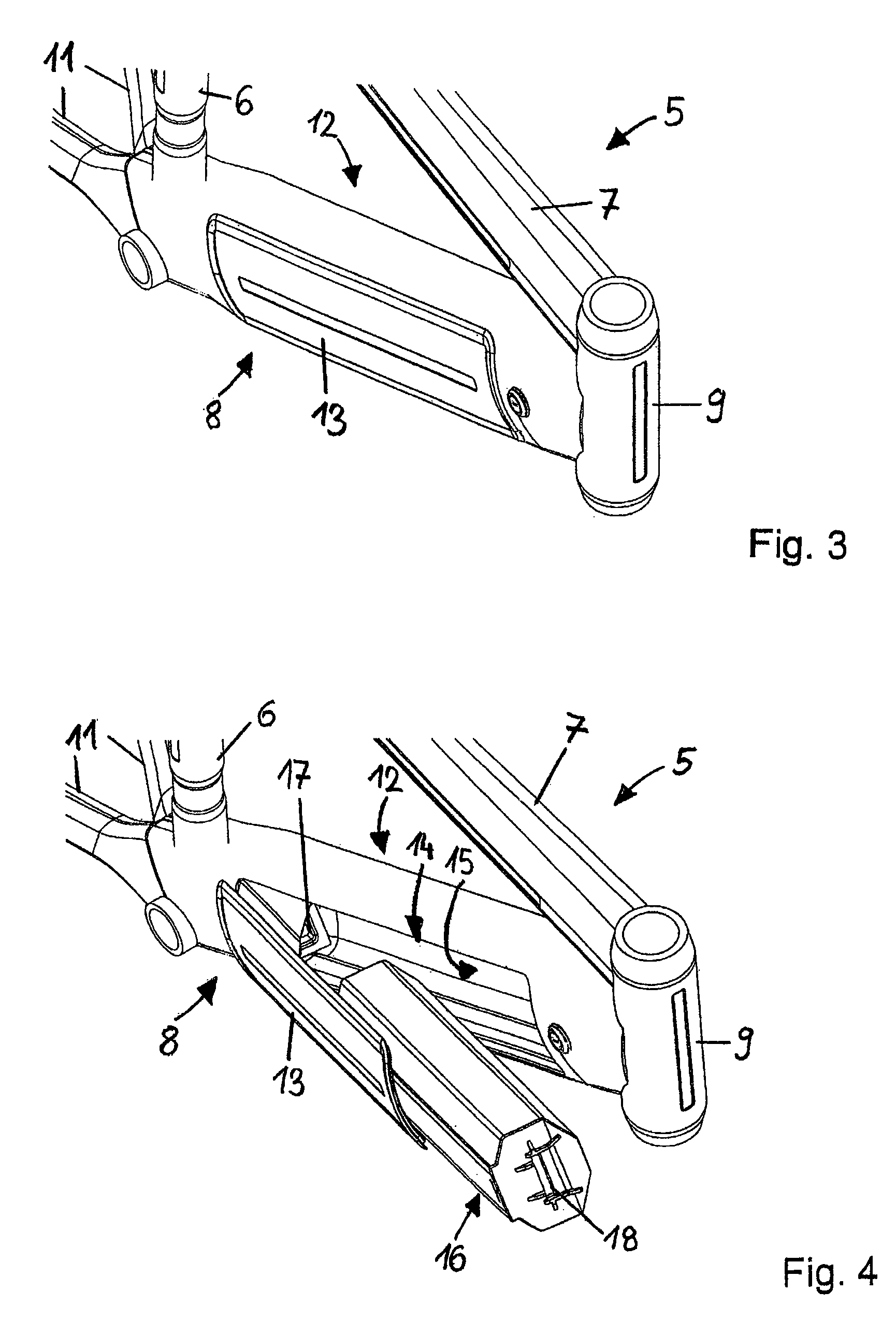
[0005]This is accomplished by a bicycle frame wherein the tube section of the bicycle frame has a lateral opening substantially extending in the direction of the extension of said tube section, wherein said battery unit is insertable into said interior space through said lateral opening. In this manner, a simple insertion and removal of the battery into and from the interior is possible transversally to the frame. At the same time, such an inserting mechanism allows the arrangement of a highly stable battery fixture over the corresponding tube length of the interior. The dependent claims indicate preferred embodiments of this bicycle frame and of a battery unit insertable therein.
[0006]A particularly comfortable insertion and removal of the battery unit can be achieved through a swinging arrangement that provides a guidance of the manual operation and allows a precise positioning of the battery. Preferably, a hinge is arranged at one end of the interior space to which the battery unit can be coupled and swung around toward the interior space after the coupling operation. Nearby this hinge, an electric contact for the battery unit is preferably arranged such that the contact with the electromotive drive is already established when it is coupled to the hinge. In a further preferred manner, a closure lid for the lateral opening is hinged to the hinge. This offers the advantage that on one hand, the closure lid may serve to determine an inserting direction of the battery for coupling it to said hinge, and on the other hand, that a simultaneous closure of the lateral opening can be achieved during the insertion of the battery unit in the course of the swinging movement performed.

Problems solved by technology

However, such a battery container is relatively bulky and not only reduces the free space otherwise available on the bicycle frame, particularly for accommodating additional equipment such as water bottles, bicycle tools, etc., but may even impair the cycling comfort for the cyclist in the extreme case.
In addition, securing the battery inside such a container also represents a problem since it has a significant own weight but occasionally has to withstand hard shocks during cycling.
However, such a frontal opening is only convenient in folding bicycles since the front side of a non-folding bicycle is normally covered by the bicycle lights, the brake lines, etc., and is only insufficiently accessible.
Furthermore, the possibility of securing the battery in the frame interior is also limited by this frontal opening.
However, since the frontal frame opening requires a manual insertion of the battery against the action of such a force, only relatively small retaining forces may be employable in such a battery holder.

Method used


Image

  • Bicycle frame for receiving a battery unit and associated battery unit
  • Bicycle frame for receiving a battery unit and associated battery unit
  • Bicycle frame for receiving a battery unit and associated battery unit

Examples


second embodiment

[0040]FIG. 6(a) shows a tube section 12 with a tensioning device 30 according to the invention. Tensioning device 30 comprises a guide roller 33 that is coupled by a pivot arm 31 to a coil spring 34 arranged nearer to the rear wall side. On its other side, coil spring 34 is rigidly connected to tube section 12. Pivot arm 31 is hinged to an axle 19 arranged in coil spring 34 such that a movement component of guide roller 33 in the direction of extension of tube section 12 is ensured. Further illustrated is battery unit 16 that is already plugged into connecting socket 17. On the front side of battery unit 16, a circular recess 32 is formed whose shape corresponds to a segment of the circumference of guide roller 33, thereby allowing a snap engagement.

[0041]FIG. 6(b) shows battery unit 16 after swinging closure lid 13 around until the front side of battery unit 16 enters into contact with guide roller 33. As battery unit 16 is further introduced, guide roller 33 is set into rotation a...

third embodiment

[0043]FIG. 7(a) shows a tube section 12 with a tensioning device 35 according to the invention. Tensioning device 35 comprises a guide roller 33. Furthermore, battery unit 17 plugged into connecting socket 16 is illustrated again.

[0044]FIG. 7(b) shows tube section 12 illustrated in FIG. 7(a) in a sectional view according to the sectional plane indicated in FIG. 7(a). In this Figure it is seen that tensioning device 35 is associated to a spring pair 36 arranged at the end of interior space 15.

[0045]FIG. 7(c) shows tube section 12 according to the view of FIG. 7(a) with the front side of battery unit 16 brought into contact with guide roller 33. Here also, a further swinging movement of closure lid 13 results in an increasing force application to battery unit 16 until its circular recess engages in guide roller 33, as shown in FIG. 7(d).

fourth embodiment

[0046]FIG. 8(a) shows a tube section 12 with a tensioning device 40 according to the invention. Tensioning device 40 comprises a rotatably mounted axle 41 that is manually actuatable from the outside. Axle 41 has a twisting bolt 42 hinged thereto, and to the opposite side of the latter, a locking pin 43 is hinged. Further illustrated is battery unit 16 that is already inserted in interior space 15. Tensioning device 40 is in the untensioned state.

[0047]FIG. 8(b) shows tube section 12 after a rotation of axle 41 whereby the twisting bolt is moved toward the battery unit and the locking pin abuts to the front side of battery unit 16 such that an increasing tension force is applied to battery unit 16 as axle 41 is further rotated.

[0048]FIGS. 9(a) and 9(b) show closure lid 13 in a top view with a guide pin 45 fastened thereto. The guide pin engages in rail 47 of a guide plate 46 that is fastened to a tube section 12. In the outer end area of rail 47, a detent structure 48 is formed by w...


PUM


Abstract

The invention relates to a bicycle frame comprising a tube section having an interior space for receiving at least one battery unit that is suitable as a source of energy for an electromotive bicycle drive, as well as to a battery unit insertable therein.To provide an easy operation and at the same time a highly stabilized placement of the battery, it is suggested that said tube section is provided with a lateral opening substantially extending in the direction of extension of said tube section, wherein said battery unit is insertable into said interior space through said lateral opening.

Description

FIELD OF THE INVENTION[0001]The present invention relates to a bicycle frame comprising a tube section having an interior space for receiving at least one battery unit that is suitable as a source of energy for an electromotive bicycle drive. The invention further relates to a battery unit for insertion into such a bicycle frame.BACKGROUND OF THE INVENTION[0002]Electric motors are used in bicycles both as a full drive and as an auxiliary or hybrid drive, the electric motor, when required, acting either as a complete bicycle drive or to assist the pedal drive actuated by the cyclist. As sources of energy for such a motor, batteries, more particularly rechargeable batteries are required, which are conventionally fastened to the bicycle frame in a suitable location. To this end, the bicycle frame is usually provided with a battery container. However, such a battery container is relatively bulky and not only reduces the free space otherwise available on the bicycle frame, particularly f...

Claims


Application Information

Patent Timeline
Patent Type & Authority Patents(United States)
IPC IPC(8): B62K19/30B60R16/04B62M6/90B60K1/04B62M6/40
CPCB62K19/30B60R16/04B60K1/04B60Y2200/13B62M6/90
Inventor BINGGELI, THOMASISENSCHMID, DOMINICZBAREN, ANDREASGRAF, URSAESCHLIMANN, MARCELRUSCH, CHRISTOPHCOOPER, GARY
Owner THOMUS VELOSHOP
Learn More