Screw bone implant

Pending Publication Date: 2022-04-07
ANJALI INVESTMENTS LLC
View PDF0 Cites 0 Cited by
  • Summary
  • Abstract
  • Description
  • Claims
  • Application Information

AI Technical Summary

Benefits of technology

The patent describes an implant that can be used to replace a damaged spinal joint. The implant has low-pitch threads and low crests, which helps to minimize the difference between its inner and outer diameters. The implant can also have variable pitch threads to allow for distraction or compression of the joints. The main technical effects of the implant are simplified insertion and improved joint preservation.

Problems solved by technology

However, posterior based surgery has the following major disadvantages: dissection or approach related post-operative pain and large or limited arthrodesis option (for example, lateral mass screws and surface area available for fusion).
However, certain unique risks still remain with anterior surgery: injury to esophagus, injury to trachea, dysphagia / dysphonia, injury to recurrent laryngeal nerves, carotid artery injury, internal jugular vein injury, vagus nerve injury, adjacent level disease, non-unions, implant failure, implant prominence, dural injury, spinal cord injury to name a few.
These devices all require some degree of malleting for insertion.
The major issue with any of these implants, despite the length of the screws on average being 10-16 mm, is related to the approach or exposure: an extremely wide dissection is required which may increase post-operative pain / disability and may increase the risk of infection.

Method used


Image

  • Screw bone implant
  • Screw bone implant
  • Screw bone implant

Examples


Embodiment Construction

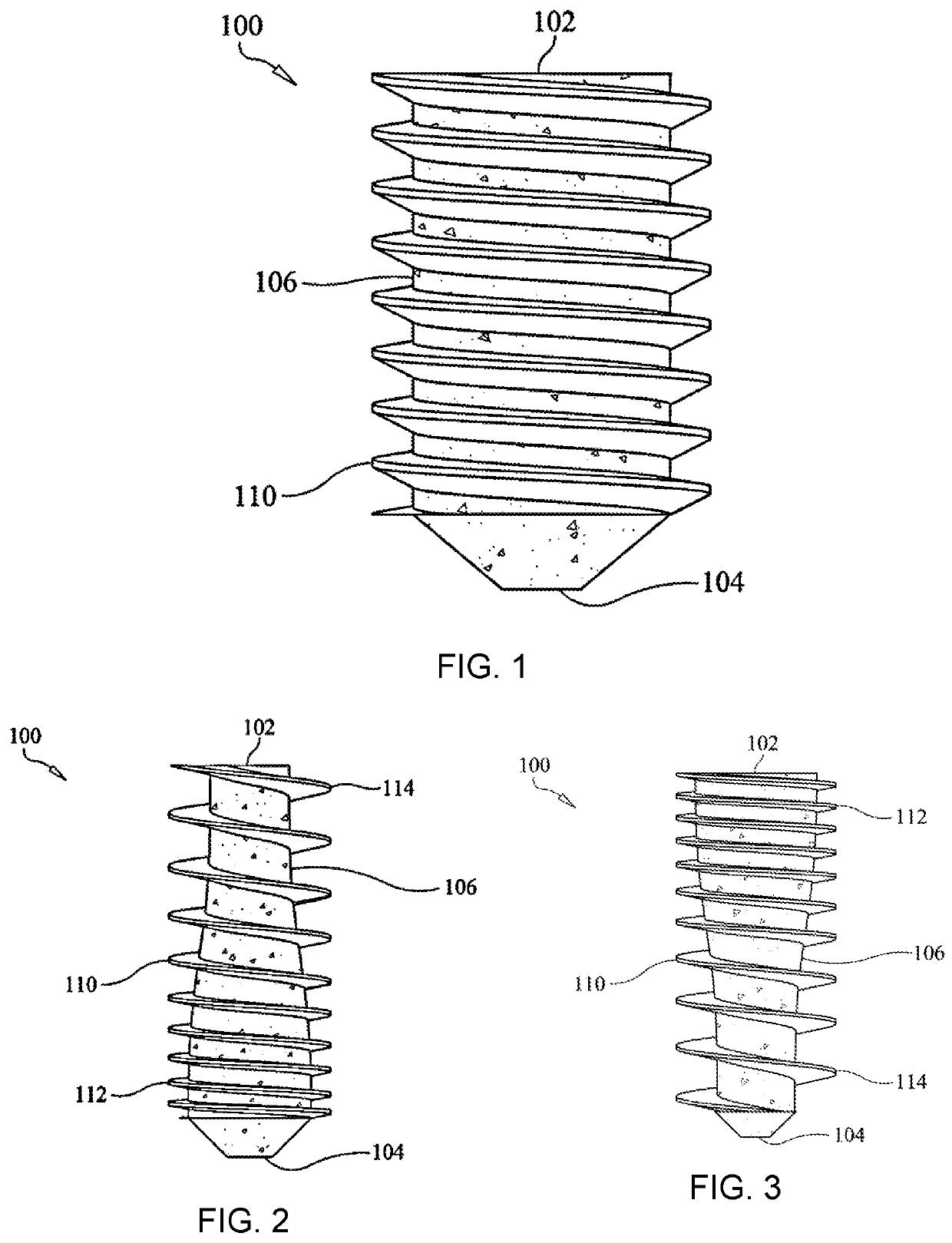
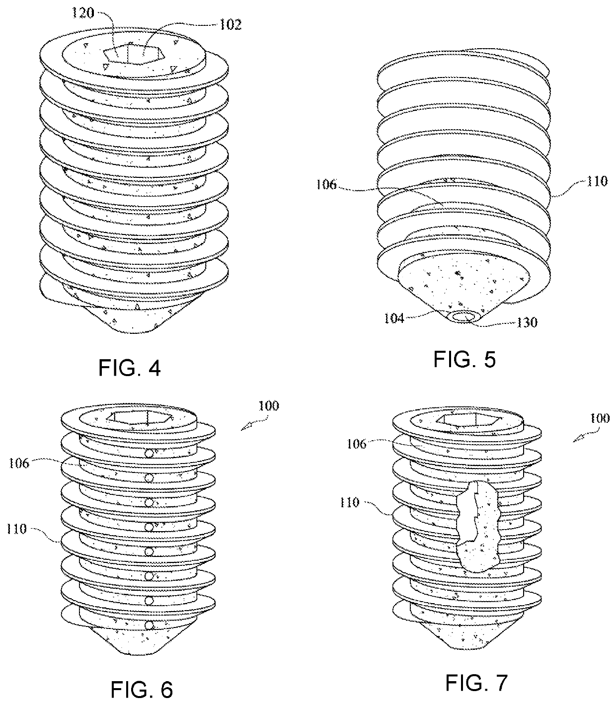
[0031]This invention provides an implant for fusion of cervical spinal vertebrae, wherein the implant is a fully threaded screw with a cylindrical body as shown in FIGS. 1-7, having a uniform major diameter. For orientation, the screw has a distal first end that is flattened, rounded, or blunted for insertion into bone tissue. The screw has a proximal second end that is headless and has a drive engagement feature, such as a hexagonal head, star head, or Phillips head. The designations of distal and proximal are in relation to the surgeon.

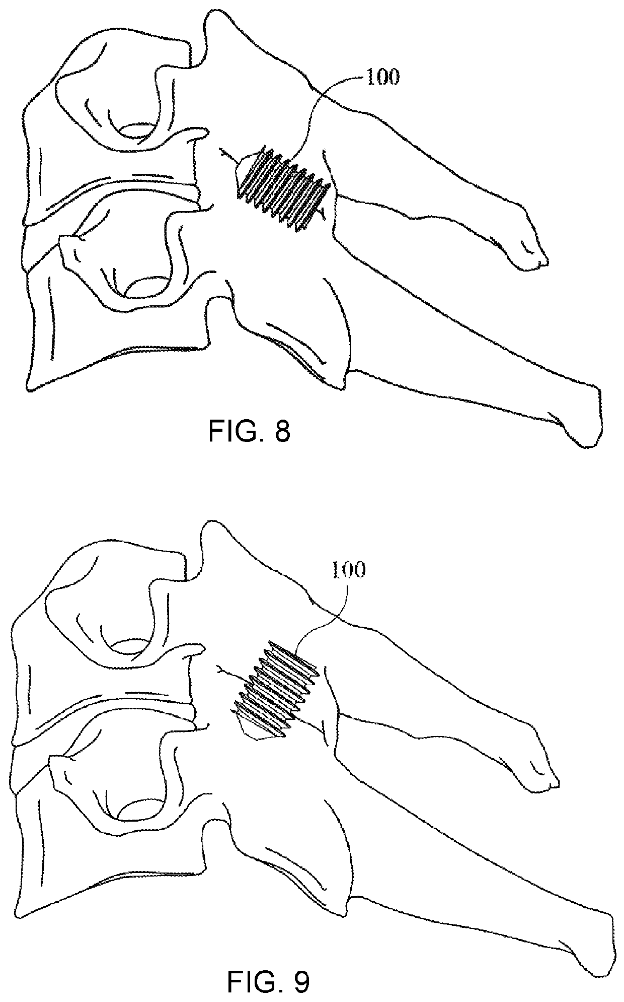
[0032]The inventive implants may be used for distraction, fusion, and bone compression of adjacent bones or bone fragments, including vertebrae. In an embodiment, the screws are inserted into the posterior facet joint between two vertebrae. Alternatively, the screws can be inserted across a facet joint using a drilled hole and optionally a guide wire. In contrast to the prior art devices discussed above, such as the CAVUX®, HONOUR® ORB, Valeo® II C,...


PUM


Abstract

A screw implant is provided for the distraction, fusion, or compression of two adjacent bone structures or two adjacent bone fragments. The implant is a fully threaded screw with a headless proximal end having a drive engagement feature and a blunt distal end for insertion into bone or related tissue. The implant has roughened and porous surfaces throughout and is fully coated with hydroxyapatite and / or tri-calcium phosphate to allow for bone in-growth. The implant may have uniform low pitch cortical threads, or variable pitch threads, with low pitch cortical threads on one end and larger pitch cancellous threads on the other end. The implant may be used for the distraction of spinal vertebrae. The implants may have a cannulation channel and fenestrations.

Description

CROSS REFERENCE TO RELATED APPLICATION[0001]This patent application claims the benefit of U.S. Patent Application 62 / 789,483 filed Jan. 7, 2019.FIELD OF THE INVENTION[0002]The invention pertains to fully threaded screws as surgical implants for the distraction, compression, and / or fusion of vertebrae and other bones, joints, or bone segments.BACKGROUND[0003]Cervical surgery since the late 1950s and early 1960s has steadily transitioned from primarily posterior based to primarily anterior based. Posterior based surgery has the following major advantages: minimal critical structures in the surgical field, familiar anatomy, and access to multiple levels. However, posterior based surgery has the following major disadvantages: dissection or approach related post-operative pain and large or limited arthrodesis option (for example, lateral mass screws and surface area available for fusion). Anterior based cervical surgery addresses some of the deficits, particularly pain and infection rate...

Claims


Application Information

Patent Timeline
IPC IPC(8): A61B17/86A61B17/70
CPCA61B17/864A61B17/70A61B17/866A61B17/863A61B17/861A61B17/8645A61B17/869A61B2017/00933A61F2/4465A61B17/7064
Inventor PATEL, AMIT R.
Owner ANJALI INVESTMENTS LLC
Why Eureka
Try Eureka