Maintenance terminal of disk array device

a technology of disk array device and maintenance terminal, which is applied in the direction of memory address/allocation/relocation, program control, instruments, etc., can solve the problems that the remote terminal cannot check is not easy to refer to the setting contents, so as to facilitate the verification of the setting contents of the disk array devi

Inactive Publication Date: 2007-05-29
HITACHI LTD
View PDF19 Cites 0 Cited by
  • Summary
  • Abstract
  • Description
  • Claims
  • Application Information

AI Technical Summary

Benefits of technology

[0009]It is therefore an object of the present invention to provide a maintenance terminal for a disk array device capable of performing setting of the disk array device and-easily confirming the setting contents of the disk array device.
[0010]In order to solve the above-described problem and achieve the object of the invention, the maintenance terminal for a disk array of this invention is provided with a plurality of setting terminals into which a conduction pin is selectively inserted, to selectively change the setting of the disk array in a network. Since the conduction pin can be selectively inserted into or removed from a plurality of setting terminals, a simple insertion and removal operation can make setting of the disk array device in the network.
[0013]According to the invention, a maintenance terminal for a disk array device is provided which can make setting of the disk array device and can easily confirm the setting contents of the disk array device. In particular, a plurality of light emitting elements can display a specific pattern representative of the setting state of the disk array device in the network for connection check in a normal state. It is possible to change the illumination pattern by selectively inserting the conduction pin into the plurality of setting terminals or in response to a remote request from an operation terminal or a host.

Problems solved by technology

However, when a connection failure occurs at such a disk array device, particularly when a connection failure from the remote terminal occurs, the remote terminal cannot check the setting contents of the disk array device because there is no display screen.
In this manner, it is not easy to refer to the setting contents.

Method used


Image

  • Maintenance terminal of disk array device
  • Maintenance terminal of disk array device
  • Maintenance terminal of disk array device

Examples


first embodiment

[0034]First, description will be made on initialization setting according to the

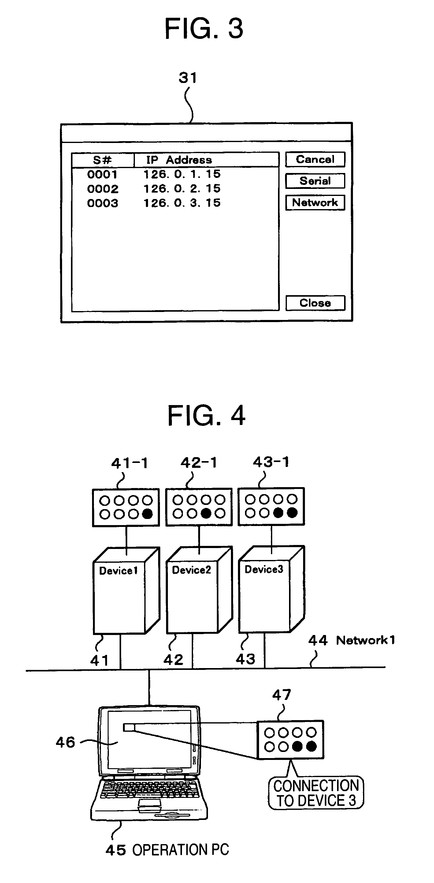
[0035]In the interconnection shown in FIG. 4, the initialization setting is performed if it is not possible to perform remote connection via the network 44 from the operation personal computer (PC) 45 to each maintenance terminal of the disk array devices 41, 42 and 43. With the initialization setting, a failure can be eliminated.

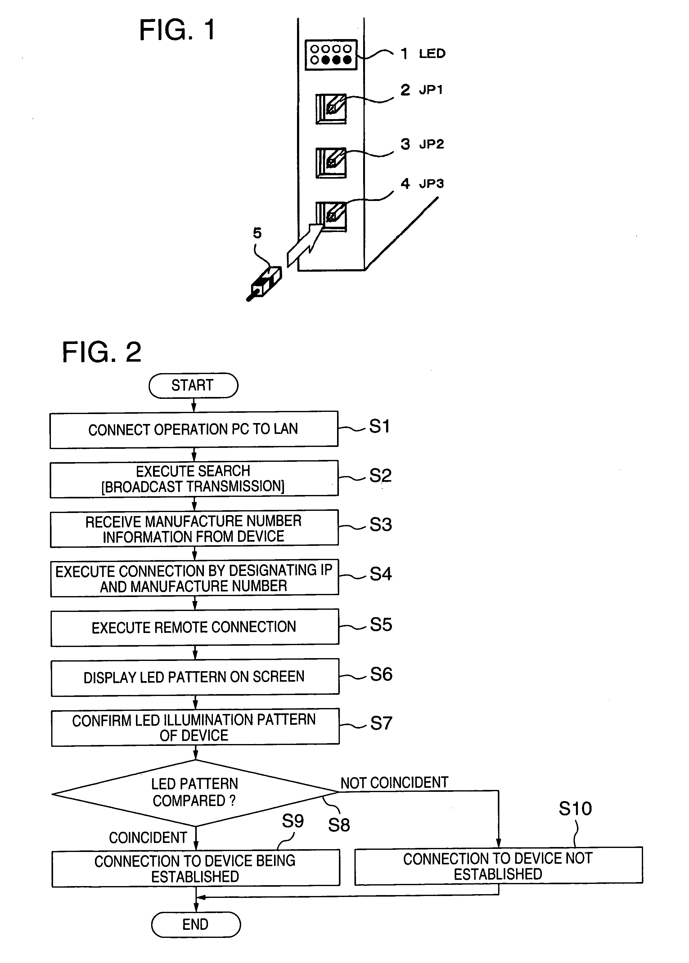
[0036]In order to realize the above-described remote connection, an IP address representative of the network identification number of each maintenance terminal mounted on the disk array devices 41, 42 and 43 is forcibly initialized, and a password for allowing an input operation to each of the disk array devices 41, 42 and 43 is initialized. For this initialization, the conduction jumper pins 5 may be inserted into all the jumper connectors (JP1), (JP2) and (JP3).

second embodiment

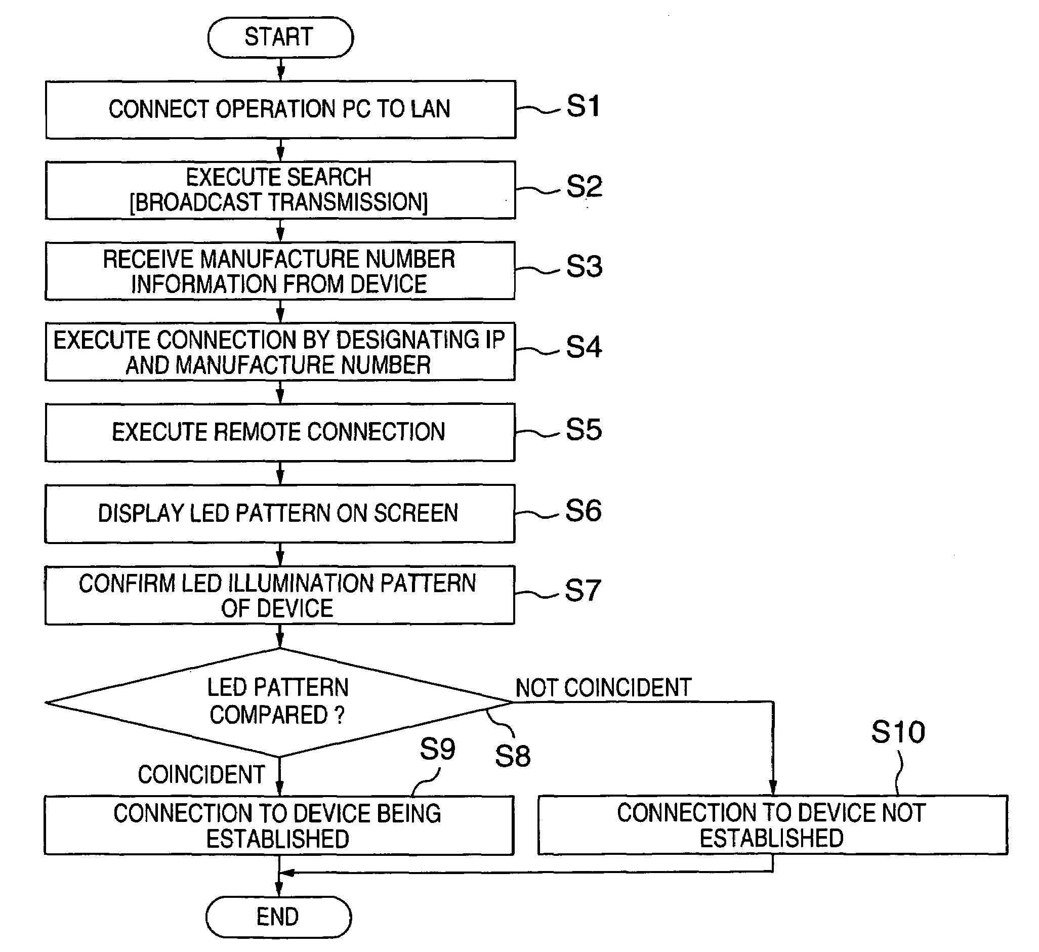
[0037]Next, description will be made on IP address display and IP address illumination according to the invention.

[0038]In the interconnection shown in FIG. 4, if it is not possible to perform remote connection via the network 44 from the operation personal computer (PC) 45 to each maintenance terminal of the disk array devices 41, 42 and 43, it is necessary to refer to the IP address of each maintenance terminal mounted on the disk array devices 41, 42 and 43. In this case, the conduction jumper pins 5 are inserted into the jumper connectors (JP1), (JP2) and (JP3) of each maintenance terminal mounted on the disk array devices 41, 42 and 43, to display the IP address by the light emitting diode arrays (LED) 41-1, 42-1 and 43-1. In this manner, by displaying the IP address, the reason of inability of the remote connection can be inspected.

[0039]First, a first example of displaying an IP address will be described.

[0040]A number represented by one byte of binary numbers is obtained by ...

third embodiment

[0049]Description will be made on the status display and error code illumination for each status according to the invention.

[0050]In this embodiment, the current status and an error code of each maintenance terminal installed in the disk array devices 41, 42 and 43 are displayed. An example of the display method is illustrated in FIG. 11. Referring to FIG. 11, the meanings 116-2 and statuses 116-3 shown in Table 116 are allocated in correspondence with the illumination display events of LED 0 to LED 7: from the LED0 of the light emitting diode array (LED) 115 indicated at 115-0, LED3 indicated at 115-3, LED4 indicated at 115-4, and to LED 7 indicated at 115-7.

[0051]In Table 116, turn-on of LED0 means that the maintenance terminal is in service and LED0 is in the on-state when the maintenance terminal is activated. Turn-on of LED1 means a modify mode and LED1 is in the on-state during the modify mode. Turn-on of LED2 means that a Web console can be used and LED2 turns on in a use ena...


PUM

PropertyMeasurementUnit
current statusaaaaaaaaaa
poweraaaaaaaaaa

Abstract

A maintenance terminal for a disk array device is provided which can make setting of the disk array device and can easily confirm the setting contents. The maintenance terminal for the disk array device has three jumper connectors as setting terminals into which a conduction pin is inserted. The maintenance terminal also has eight light emitting diodes disposed in two rows and being capable of turning on and off in correspondence with a setting state of the disk array device in a network selectively changed through insertion of the conduction pin into the setting terminals.

Description

CROSS-REFERENCE TO RELATED APPLICATION[0001]The present application claims priority from Japanese application JP2004-069305 filed on Mar. 11, 2004, the content of which is hereby incorporated by reference into this application.BACKGROUND OF THE INVENTION[0002]A) Field of the Invention[0003]The present invention relates to a disk array device used as a maintenance terminal.[0004]B) Description of the Related Art[0005]In a disk array device, a maintenance terminal attached thereto, such as a service processor (SVP), has been used conventionally. In addition to the maintenance terminal, a remote console (RMC) is provided which is installed at a remote site and connected to a plurality of disk array devices via a network. This remote terminal controls the operation and maintenance of a plurality of devices. Refer to Japanese Patent Laid-open Publication No. 2002-157211.[0006]Since the operation and maintenance of the device can be controlled by using a display and a keyboard at the remo...

Claims


Application Information

Patent Timeline
Patent Type & Authority Patents(United States)
IPC IPC(8): G06F15/177G06F12/06G06F12/08G06F9/22G06F9/44G06F3/06G06F11/32G06F13/00G11B33/10H04L29/12
CPCG06F11/325
Inventor SEKINE, KENJIYAMAMOTO, MASANOBU
Owner HITACHI LTD
Why Eureka
Try Eureka