Maintenance terminal of disk array device
a technology of disk array device and maintenance terminal, which is applied in the direction of error detection/correction, program control, instruments, etc., can solve the problems that the remote terminal cannot check is not easy to refer to the setting contents, so as to facilitate the verification of the setting contents of the disk array devi
- Summary
- Abstract
- Description
- Claims
- Application Information
AI Technical Summary
Benefits of technology
Problems solved by technology
Method used
Image
Examples
first embodiment
[0034] First, description will be made on initialization setting according to the
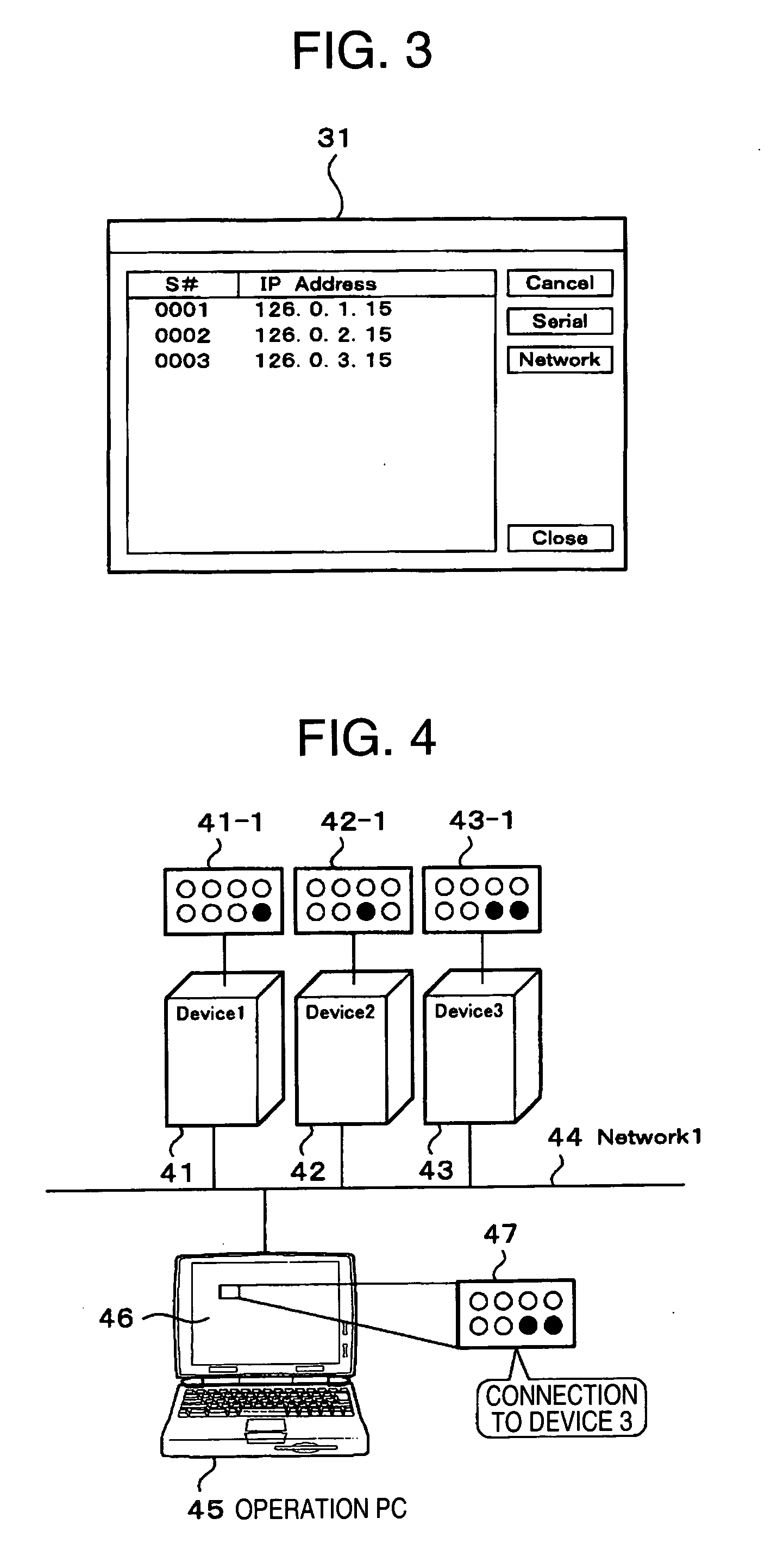
[0035] In the interconnection shown in FIG. 4, the initialization setting is performed if it is not possible to perform remote connection via the network 44 from the operation personal computer (PC) 45 to each maintenance terminal of the disk array devices 41, 42 and 43. With the initialization setting, a failure can be eliminated.
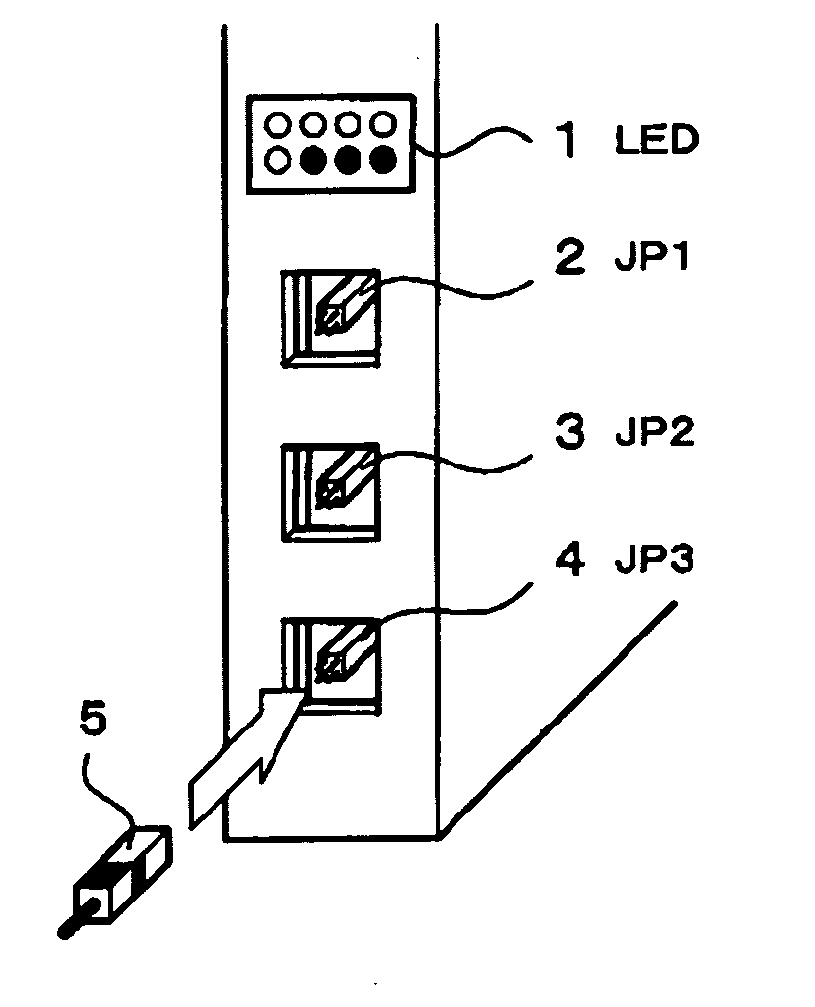
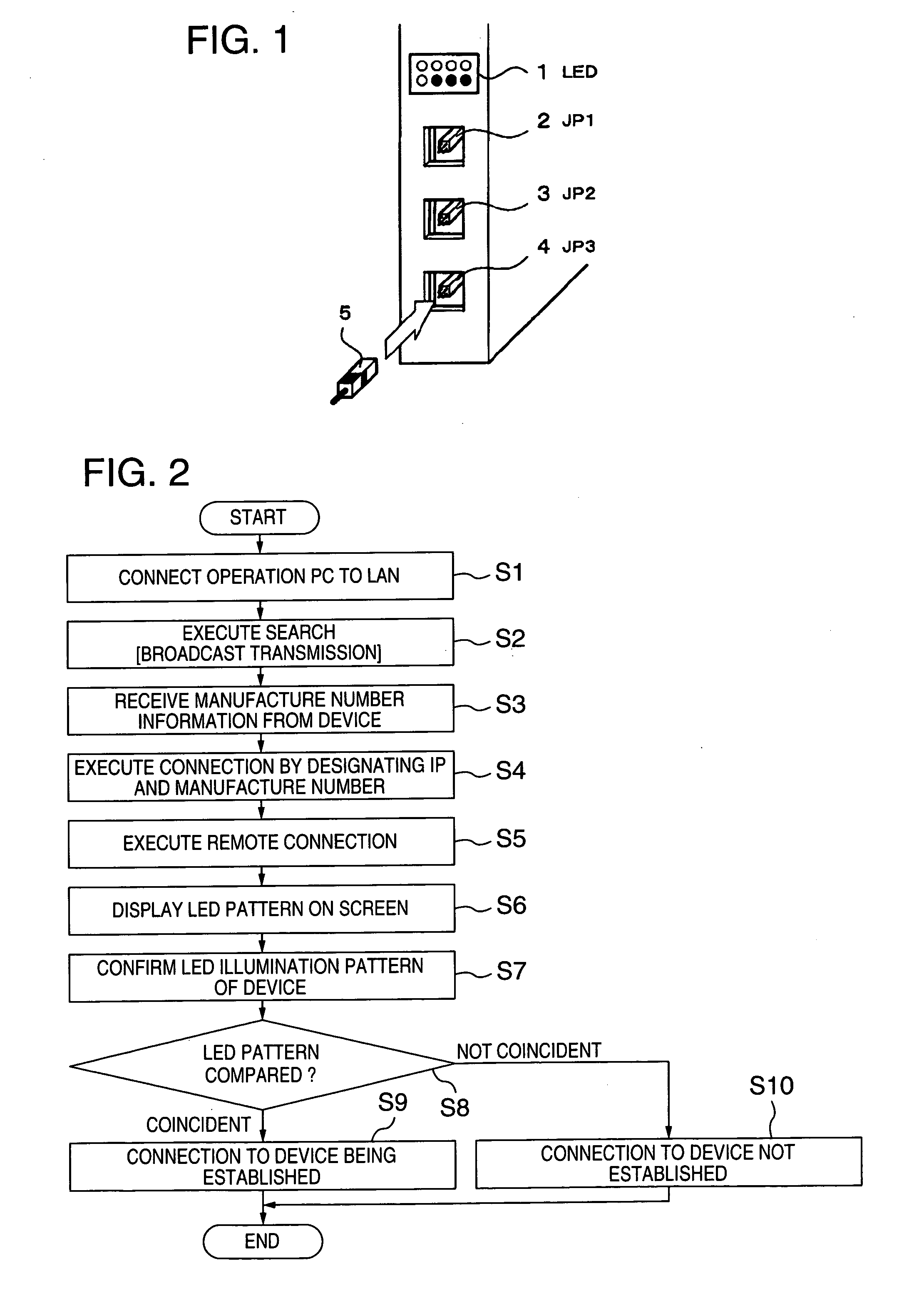
[0036] In order to realize the above-described remote connection, an IP address representative of the network identification number of each maintenance terminal mounted on the disk array devices 41, 42 and 43 is forcibly initialized, and a password for allowing an input operation to each of the disk array devices 41, 42 and 43 is initialized. For this initialization, the conduction jumper pins 5 may be inserted into all the jumper connectors (JP1), (JP2) and (JP3).
second embodiment
[0037] Next, description will be made on IP address display and IP address illumination according to the invention.
[0038] In the interconnection shown in FIG. 4, if it is not possible to perform remote connection via the network 44 from the operation personal computer (PC) 45 to each maintenance terminal of the disk array devices 41, 42 and 43, it is necessary to refer to the IP address of each maintenance terminal mounted on the disk array devices 41, 42 and 43. In this case, the conduction jumper pins 5 are inserted into the jumper connectors (JP1), (JP2) and (JP3) of each maintenance terminal mounted on the disk array devices 41, 42 and 43, to display the IP address by the light emitting diode arrays (LED) 41-1, 42-1 and 43-1. In this manner, by displaying the IP address, the reason of inability of the remote connection can be inspected.
[0039] First, a first example of displaying an IP address will be described.
[0040] A number represented by one byte of binary numbers is obtain...
third embodiment
[0049] Description will be made on the status display and error code illumination for each status according to the invention.
[0050] In this embodiment, the current status and an error code of each maintenance terminal installed in the disk array devices 41, 42 and 43 are displayed. An example of the display method is illustrated in FIG. 11. Referring to FIG. 11, the meanings 116-2 and statuses 116-3 shown in Table 116 are allocated in correspondence with the illumination display events of LED 0 to LED 7: from the LED0 of the light emitting diode array (LED) 115 indicated at 115-0, LED3 indicated at 115-3, LED4 indicated at 115-4, and to LED 7 indicated at 115-7.
[0051] In Table 116, turn-on of LED0 means that the maintenance terminal is in service and LED0 is in the on-state when the maintenance terminal is activated. Turn-on of LED1 means a modify mode and LED1 is in the on-state during the modify mode. Turn-on of LED2 means that a Web console can be used and LED2 turns on in a use...
PUM
| Property | Measurement | Unit |
|---|---|---|
| current status | aaaaa | aaaaa |
| power | aaaaa | aaaaa |
Abstract
Description
Claims
Application Information
 - R&D
- Intellectual Property
- Life Sciences
- Materials
- Tech Scout
- Unparalleled Data Quality
- Higher Quality Content
- 60% Fewer Hallucinations
Browse by: Latest US Patents, China's latest patents, Technical Efficacy Thesaurus, Application Domain, Technology Topic, Popular Technical Reports.
© 2025 PatSnap. All rights reserved.Legal|Privacy policy|Modern Slavery Act Transparency Statement|Sitemap|About US| Contact US: help@patsnap.com


