
Coaxial barrel fittings and couplings with ground establishing traveling sleeves

a technology of traveling sleeves and barrel fittings, which is applied in the direction of coupling devices, coupling contact members, coupling devices, etc., can solve the problems of easy compromise of electrical pathways with typical known female connector designs, improper installation of connectors, and inability to connect with each other, so as to achieve the effect of minimizing resistive losses

Active Publication Date: 2014-11-18
PERFECTVISION MFG
View PDF113 Cites 30 Cited by
  • Summary
  • Abstract
  • Description
  • Claims
  • Application Information

AI Technical Summary

Benefits of technology

[0030]Thus the primary object of our invention is to provide a female connector end construction, and a female barrel connector with such ends, that overcome electrical connection problems associated with improper connector torquing or installation.
[0033]A related object is to provide a connector of the character described that establishes effective continuity and / or grounding during installation of the male connector to the various types of threaded female connections, even though applied torque may fail to meet specifications.
[0037]Another important object is to minimize resistive losses in a coaxial cable junction.

Problems solved by technology

However, the extremely high bandwidths and frequencies distributed in conjunction with modern satellite installations necessitates a variety of strict quality control factors.
Despite efforts in the industry to provide reliable, wide-band connectors and accessories, problems often result where connectors are improperly installed.
Absent proper application torque, the electrical grounding path can be compromised and can become intermittent.
In any case, resulting electrical pathways with typical known female connector designs are easily compromised when application torque is improper.

Method used


Image

  • Coaxial barrel fittings and couplings with ground establishing traveling sleeves
  • Coaxial barrel fittings and couplings with ground establishing traveling sleeves
  • Coaxial barrel fittings and couplings with ground establishing traveling sleeves

Examples


Embodiment Construction

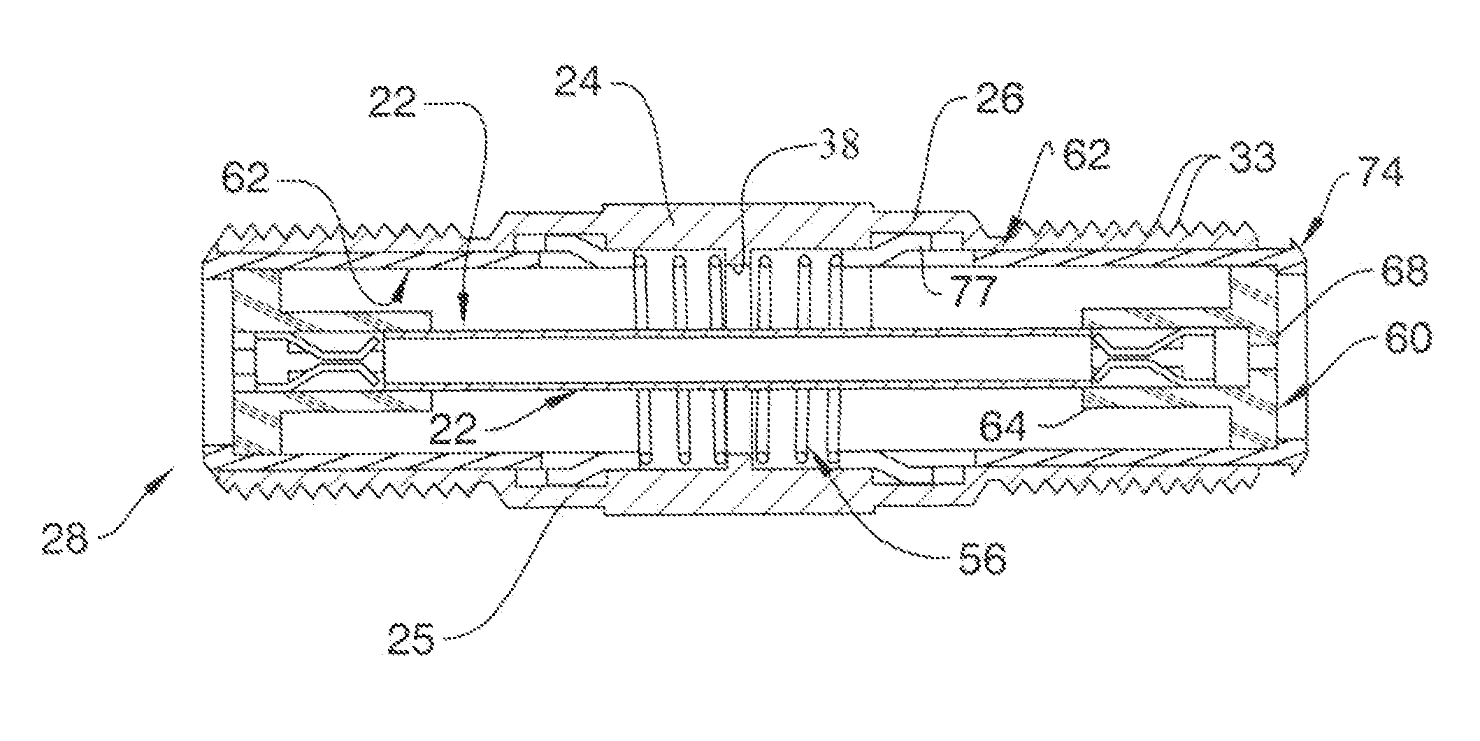
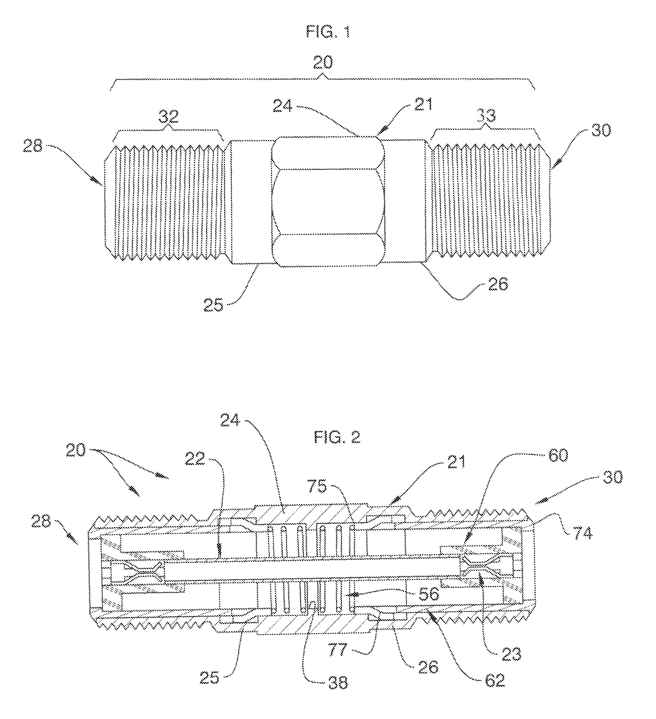
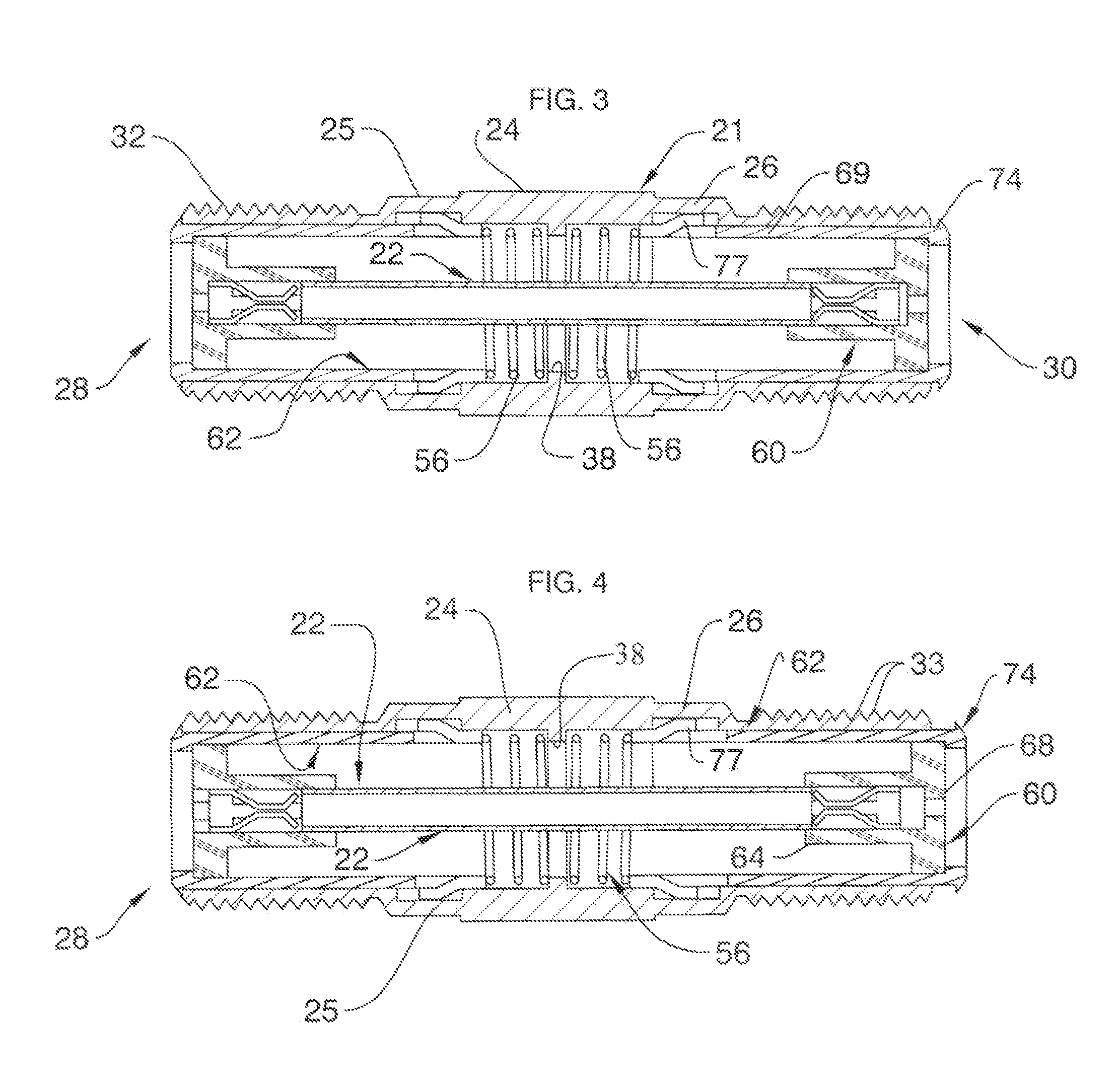
[0062]Detailed herein are various connector embodiments, all of which include female sockets adapted to be engaged by a coaxial connector, nominally an F-connector. The three barrel connectors described hereinafter preferably employ an internal contact tube constructed in accordance with U.S. Pat. No. 7,931,509, the disclosure of which is hereby incorporated by reference as if fully set forth herein. Various tubular contact tubes (also known as “center pins”) are known in the art, and this invention is not limited to any particular center pin design. The connector embodiments described herein that are equipped with a single female socket preferably use a modified contact tube having one end configured as in U.S. Pat. No. 7,931,509. A wide variety of F-connectors may be used with any of the embodiments disclosed herein. Coaxial F-connectors described in U.S. Pat. Nos. 7,513,795 and 7,841,896 are ideal. Further, while it is to be noted that connectors depicted herein are employed with...


PUM


Abstract

Barrel connectors, a right angled adaptor and a single ended fitting include at least one axially displaceable traveling sleeve for insuring electrical continuity with coaxial connector, nominally an F-connector. Each barrel connector described comprises a rigid, metallic hollow body housing an internal contact tube. At least one coiled spring is retained within the body. At least one elongated, tubular traveling sleeve is coaxially disposed within each body end and normally biased outwardly by the springs. The metallic traveling sleeves comprise an elongated shank that contacts the spring, and a head that seats against the connector body ends during installation. Catches or rings defined upon or mounted to travelling sleeve shanks are received within suitable grooves for anchoring the traveling sleeves while facilitating limited axial displacements. The traveling sleeves, and the contact tube therewithin, normally are biased outwardly so that even limited torquing of an F-connector will establish a ground path.

Description

CROSS REFERENCE TO RELATED APPLICATION[0001]This application is based upon, and claims priority from, prior pending U.S. Provisional Patent application Ser. No. 61 / 628,141, Filed Oct. 25, 2011, entitled “Coaxial Barrel Fittings with Ground Establishing Traveling Sleeves” by coinventors Robert J. Chastain and Glen D. Shaw.BACKGROUND OF THE INVENTION[0002]1. Field of the Invention[0003]The present invention relates generally to coaxial cable connectors, couplings and fittings such as barrel connectors. More particularly, the present invention relates to socketed, female-type coaxial fittings adapted to establish a proper ground when coupled to male connectors. Known prior art is classified in United States Patent Class 439, Subclasses 497, 578, 851, and 852.[0004]2. Description of the Related Art[0005]Popular cable television systems and satellite television receiving systems depend upon coaxial cable for distributing signals. As is known in the satellite TV arts, coaxial cable in suc...

Claims


Application Information

Patent Timeline
Patent Type & Authority Patents(United States)
IPC IPC(8): H01R9/05
CPCH01R24/542H01R24/545H01R13/15
Inventor CHASTAIN, ROBERT J.SHAW, GLEN DAVID
Owner PERFECTVISION MFG
Learn More