Dual connector interface for capacitive or conductive coupling

a capacitive or conductive coupling and dual connector technology, applied in the direction of coupling device connection, magnetic body, waveguide type device, etc., can solve the problem of degrading the electrical performance of an entire rf system

Inactive Publication Date: 2014-11-18
COMMSCOPE TECH LLC
View PDF19 Cites 3 Cited by
  • Summary
  • Abstract
  • Description
  • Claims
  • Application Information

AI Technical Summary

Benefits of technology

[0020]Upon interconnection with a conventional conductive male portion 20, such as a standard male 7 / 16 DIN connector, for example as shown in FIGS. 1 and 2, an inner contact 21 provided as a pin 22 of the conductive male portion 20 seats within the spring basket 6, forming a conductive electro-mechanical interconnection along the inner conductor 24, and an outer conductor protrusion 26 seats within the outer conductor groove 14, a distal end of the outer conductor contact surface 10 bottoming against an inner diameter shoulder 28 of the conductive male connector portion 34, providing a secure electro-mechanical interconnection along the outer conductor 32 and limiting the axial advance of the conductive male and female portions 20, 2 toward one another during interconnection.
[0024]The dielectric coatings of the outer and inner conductor dielectric spacers 40, 38 may be provided, for example, as a ceramic or polymer dielectric material. One example of a dielectric coating with suitable compression and thermal resistance characteristics that may be applied with high precision at very thin thicknesses is ceramic coatings. Ceramic coatings may be applied directly to the desired surfaces via a range of deposition processes, such as Physical Vapor Deposition (PVD) or the like. Ceramic coatings have a further benefit of a high hardness characteristic, thereby protecting the coated surfaces from damage prior to interconnection and / or resisting thickness variation due to compressive forces present upon interconnection. The ability to apply extremely thin dielectric coatings, for example as thin as 0.5 microns, may reduce the surface area requirement of the separated conductor surfaces, enabling the overall dimensions of the connection interface to be reduced.
[0028]Further, the inner and outer conductor dielectric spacers 38 and 40 may each be applied as described to one each of the female portion 2 and the capacitive coupling male portion 34 or both on each, with the cumulative thickness of the surfaces providing additional assurance that the thin coatings have remained in place and / or each providing additional assurance of uniformity of coverage should one or both have been damaged or mis-applied.
[0030]One skilled in the art will appreciate that the dual capacitive coupling and conductive coupling interconnection capability of the connection interface enables users to apply, for example, the female portion 2 to equipment that may benefit from future adoption of capacitive coupling as a new interconnection standard, without requiring abandonment of existing conductive coupling equipment and / or practices. Thereby, a significant increase of utility and / or versatility may be obtained at minimal additional expense and / or immediate technology adoption commitment.

Problems solved by technology

PIM is an important interconnection quality characteristic as PIM generated by a single low quality interconnection may degrade the electrical performance of an entire RF system.

Method used


Image

  • Dual connector interface for capacitive or conductive coupling
  • Dual connector interface for capacitive or conductive coupling
  • Dual connector interface for capacitive or conductive coupling

Examples


Embodiment Construction

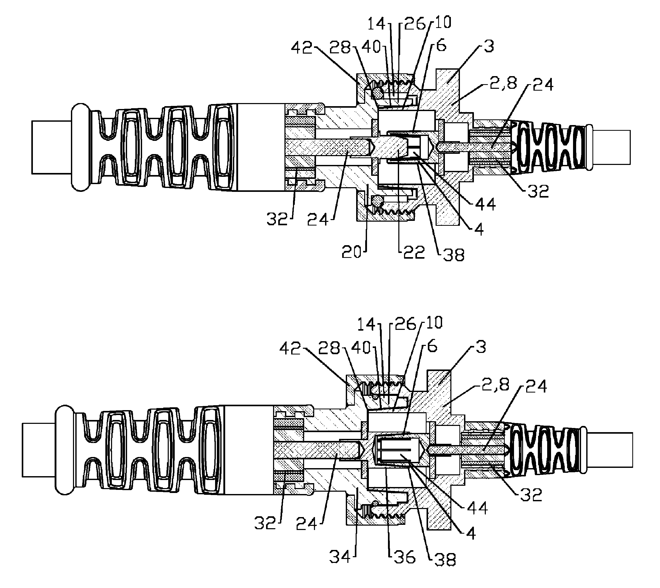
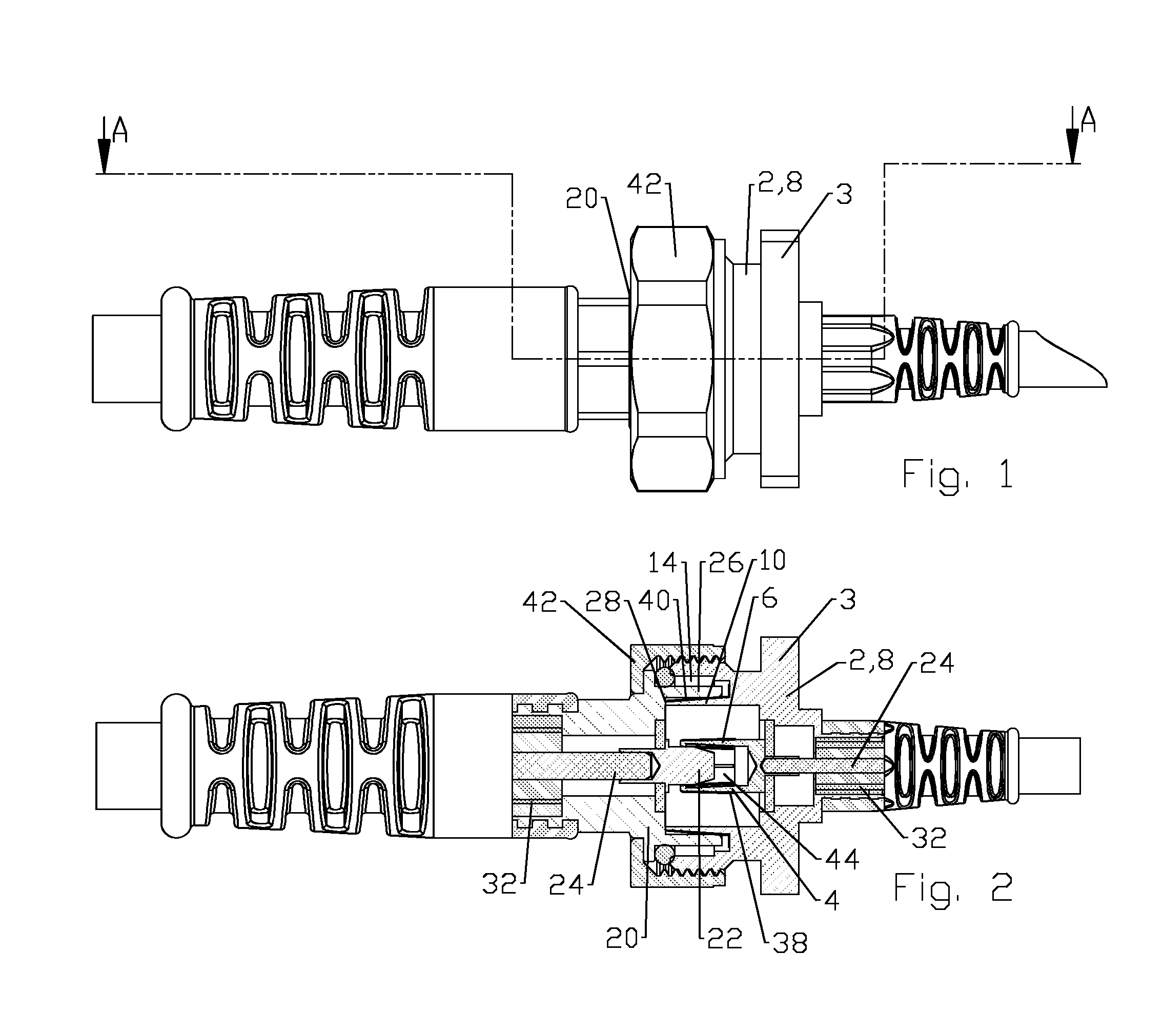
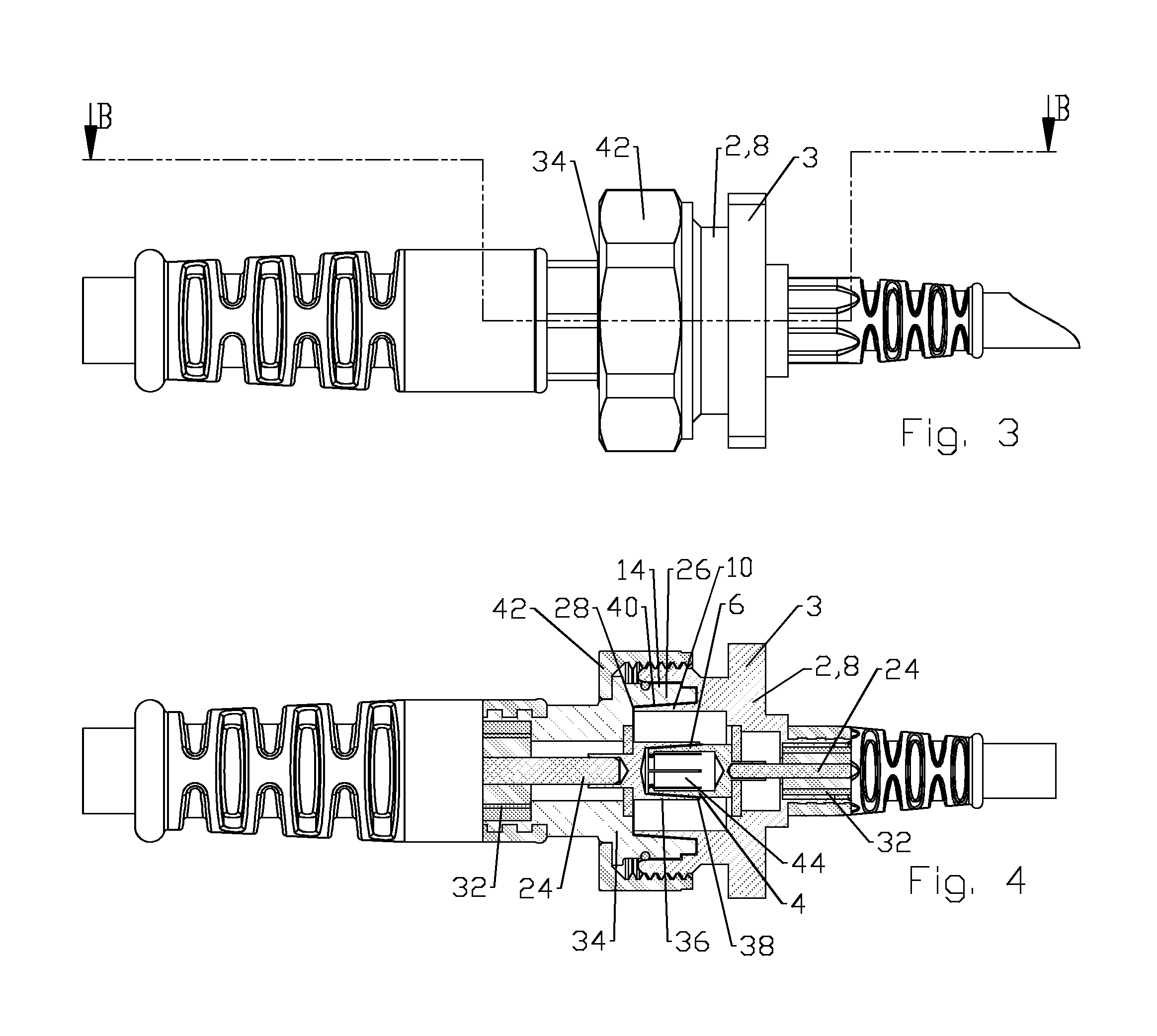
[0017]PIM reduction has also been addressed with respect to the contacting portions of a connector interface by applying capacitive coupling between these surfaces, as disclosed in commonly owned US Patent Application Publication 2013 / 0065420, titled “Connector with Capacitively Coupled Connector Interface”, by Kendrick Van Swearingen, James P. Fleming, Jeffrey D. Paynter and Ronald A. Vaccaro, published on 14 Mar. 2013 and hereby incorporated by reference in its entirety. The inventor has recognized that the cable connector market has a significant investment in connectors, cables and equipment configured for standardized electro-mechanically coupled interfaces, for example the 7 / 16 DIN coaxial connector interface, which may hinder adoption of the PIM reduction improvements available via capacitively coupled connector interfaces.

[0018]Exemplary embodiments of a coaxial connector with a connection interface suitable for interconnection with either a standardized conductive electro-m...


PUM

PropertyMeasurementUnit
conductiveaaaaaaaaaa
connection interfaceaaaaaaaaaa
outer diameteraaaaaaaaaa

Abstract

A connection interface with a female portion for interconnection with a conductive male portion or a capacitive coupling male portion interface provides conductive coupling when interconnected with the conductive male portion and capacitive coupling when coupled with the capacitive coupling male portion. The female portion may include a spring basket dimensioned to receive a pin of the conductive male portion and to seat within a socket of the conductive male portion, separated by an inner conductor dielectric spacer.

Description

BACKGROUND[0001]1. Field of the Invention[0002]This invention relates to electrical cable connectors. More particularly, the invention relates to coaxial connectors with an interconnection interface alternatively connectable with conductive or capacitive coupling between signal conducting portions of the connection interface.[0003]2. Description of Related Art[0004]Coaxial cables are commonly utilized in RF communications systems. Coaxial cable connectors may be applied to terminate coaxial cables, for example, in communication systems requiring a high level of precision and reliability.[0005]Connector interfaces provide a connect and disconnect functionality between a cable terminated with a connector bearing the desired connector interface and a corresponding connector with a mating connector interface mounted on an apparatus or a further cable. Prior coaxial connector interfaces typically utilize a retainer provided as a threaded coupling nut which draws the connector interface p...

Claims


Application Information

Patent Timeline
Patent Type & Authority Patents(United States)
IPC IPC(8): H01P5/02H01R9/05H01Q1/00H01F10/00H01G2/10
CPCH01Q1/00H01G2/10H01P5/026H01F10/00H01R9/05H04B5/0012H01R24/28
Inventor VAN SWEARINGEN, KENDRICKVACCARO, RONALD A.PAYNTER, JEFFREY DAVIDGUERIN, MICHAEL R.
Owner COMMSCOPE TECH LLC
Why Eureka
Try Eureka