Coaxial connector with capacitively coupled connector interface and method of manufacture

a capacitively coupled, coaxial connector technology, applied in the direction of coupling devices, waveguide type devices, coupling device connections, etc., can solve the problems of reducing the electrical performance of an entire rf system, and the cost prohibitive of adopting new technologies

Inactive Publication Date: 2015-06-02
COMMSCOPE TECH LLC
View PDF49 Cites 3 Cited by
  • Summary
  • Abstract
  • Description
  • Claims
  • Application Information

AI Technical Summary

Benefits of technology

[0032]Capacitive coupling between spaced apart conductor surfaces eliminates the direct electrical current interconnection between these surfaces that may otherwise be subject to PIM generation / degradation.
[0038]The dielectric coatings of the outer and inner conductor dielectric spacers 4, 14 may be provided, for example, as a ceramic or polymeric dielectric material. Examples of suitable polymeric dielectric materials include glass-filled polypropylene or polycarbonate. One example of a dielectric coating with suitable compression and thermal resistance characteristics that may be applied with high precision at very thin thicknesses is ceramic or ceramic glass coatings. These coatings may be applied directly to the desired surfaces via a range of deposition processes, such as Physical Vapor Deposition (PVD) or the like. Ceramic and ceramic glass coatings have a further benefit of a high hardness characteristic, thereby protecting the coated surfaces from damage prior to interconnection and / or resisting thickness variation due to compressive forces present upon interconnection. The ability to apply extremely thin dielectric coatings, for example as thin as 0.5 microns, may reduce the surface area requirement of the separated conductor surfaces, enabling the overall dimensions of the connection interface to be reduced.
[0046]The outer conductor dielectric spacer 4 may be formed upon the male connector body 8 (see FIGS. 15-17) and the inner conductor dielectric spacer 14 formed upon the inner contact 34 also with an insulator 40 (see FIGS. 13 and 14), prior to final assembly seating of the insulator 40 (with inner contact 34 and inner conductor 16 attached) within the bore of the male connector body 8, to improve access to the corresponding surfaces during dielectric spacer formation.
[0048]The application of capacitive coupling to the connection interface between male and female connector bodies 8, 18, enables reliable removable interconnectivity within an RF system wherein these interconnections are free of PIM. Coaxial coupling connectors adapted for mating with the standardized connection interface of existing coaxial connectors may enable cost efficient upgrade to new equipment and / or cabling providing the benefit of PIM free interconnections without requiring replacement and / or retrofitting of the entire RF system. Similarly, an RF system utilizing interconnections with a standardized capacitive coupled connector interface has the inherent flexibility of later being easily modified for operation with a conventional electromechanical interconnection should such become desired in view of changes to operating frequencies or the like.

Problems solved by technology

PIM is an important interconnection quality characteristic, as PIM generated by a single low quality interconnection may degrade the electrical performance of an entire RF system.
It may be cost prohibitive to adopt new technologies where such would require replacement and / or re-connectorizing of existing cabling and / or equipment.

Method used


Image

  • Coaxial connector with capacitively coupled connector interface and method of manufacture
  • Coaxial connector with capacitively coupled connector interface and method of manufacture
  • Coaxial connector with capacitively coupled connector interface and method of manufacture

Examples


Embodiment Construction

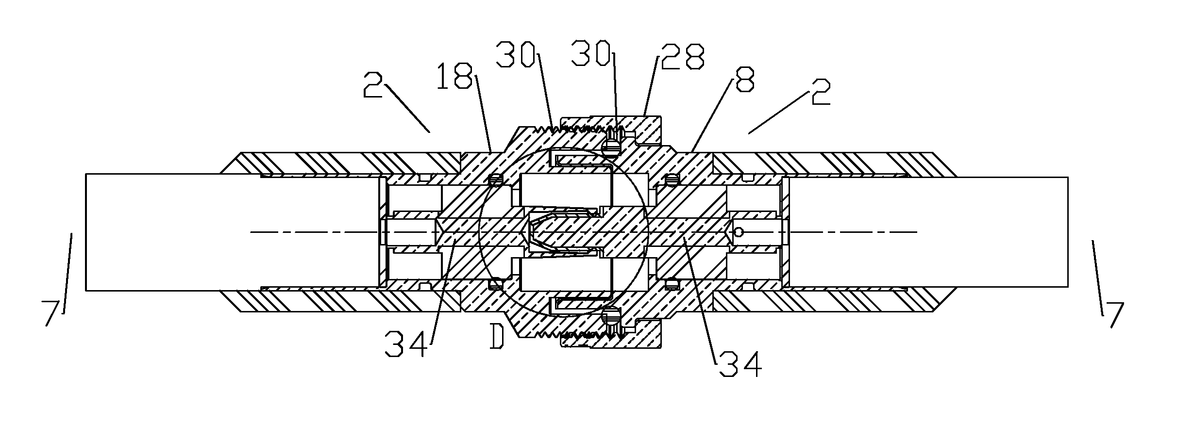
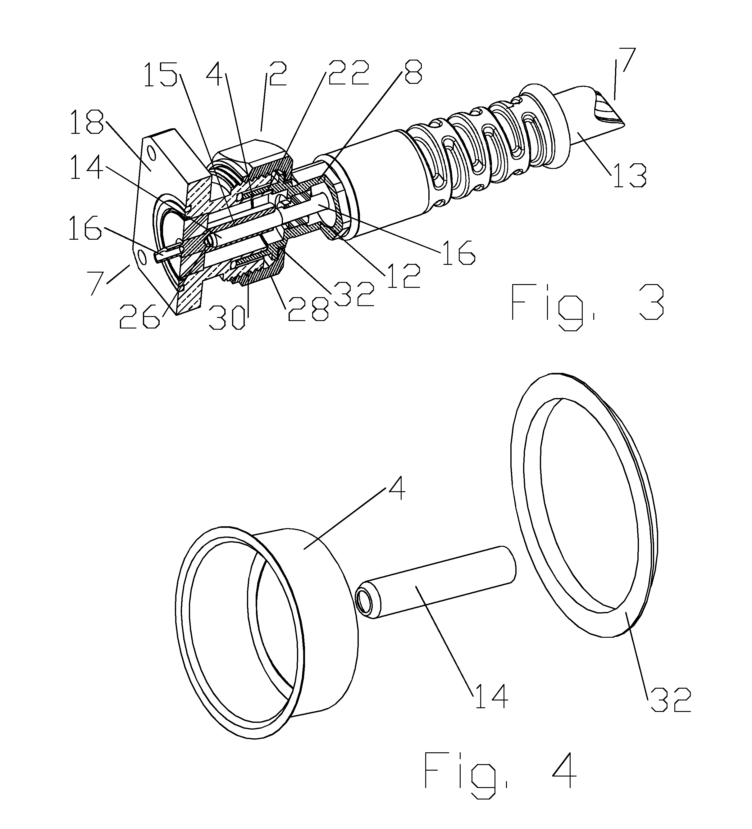
[0030]The inventors have recognized that PIM may be generated at, in addition to the interconnections between the inner and outer conductors of a coaxial cable and each coaxial connector, the electrical interconnections between the connector interfaces of mating coaxial connectors.

[0031]One skilled in the art will appreciate that a capacitive coupling interconnection may be optimized for a specific operating frequency band. For example, the level of capacitive coupling between separated conductor surfaces is a function of the desired frequency band(s) of the electrical signal(s), the surface area of the separated conductor surfaces, the dielectric constant of a dielectric spacer and the thickness of the dielectric spacer (distance between the separated conductor surfaces).

[0032]Capacitive coupling between spaced apart conductor surfaces eliminates the direct electrical current interconnection between these surfaces that may otherwise be subject to PIM generation / degradation.

[0033]As...


PUM


Abstract

A connector with a capacitively coupled connector interface for interconnection with a mating portion with a sidewall. A connector body has an outer conductor coupling surface at an interface end, covered by an outer conductor dielectric spacer. The outer conductor coupling surface is dimensioned to seat, spaced apart from the sidewall by the outer conductor dielectric spacer, when the connector body and the mating portion are in an interlocked position. A releasable retainer may be provided, the releasable retainer dimensioned to secure the connector body and the mating portion in the interlocked position.

Description

CROSS REFERENCE TO RELATED APPLICATIONS[0001]This application is a continuation-in-part of commonly owned co-pending U.S. Utility patent application Ser. No. 13 / 673,084, titled “CONNECTOR WITH CAPACITIVELY COUPLED CONNECTOR INTERFACE” filed 9 Nov. 2012 by Kendrick Van Swearingen, Ronald Alan Vaccaro, James P. Fleming and Jeffrey D Paynter, hereby incorporated by reference in its entirety.BACKGROUND[0002]1. Field of the Invention[0003]This invention relates to electrical cable connectors. More particularly, the invention relates to connectors with capacitive coupling between signal conducting portions of the connection interface, which may be compatible with standard telescoping connector interfaces.[0004]2. Description of Related Art[0005]Coaxial cables are commonly utilized in Radio Frequency (RF) communications systems. Coaxial cable connectors may be applied to terminate coaxial cables, for example, in communication systems requiring a high level of precision and reliability.[000...

Claims


Application Information

Patent Timeline
Patent Type & Authority Patents(United States)
IPC IPC(8): H01R9/05H01P5/02H01Q1/00H04B5/00
CPCH01Q1/00H04B5/0012H01P5/026H01R9/0524H01R24/40
Inventor VACCARO, RONALD ALANVAN SWEARINGEN, KENDRICKPAYNTER, JEFFREY D
Owner COMMSCOPE TECH LLC
Why Eureka
Try Eureka