MIG welder control system and method

a control system and welder technology, applied in the direction of welding apparatus, arc welding apparatus, manufacturing tools, etc., can solve the problems of affecting the establishment of arcs, and affecting the welding ar

Active Publication Date: 2014-11-18
ILLINOIS TOOL WORKS INC
View PDF17 Cites 2 Cited by
  • Summary
  • Abstract
  • Description
  • Claims
  • Application Information

AI Technical Summary

Benefits of technology

[0008]The regulation of voltage may be based upon a “firing angle” of solid state switches, such as SCRs in the power supply. Essentially, this firing angle is a time-translated location on an input AC waveform and effectively determines the voltage along the waveform at which the switches are placed in their conducting state to supply power to downstream circuitry.

Problems solved by technology

Unfortunately, the voltage feedback values of the system will vary relatively dramatically, particularly during start-up, or initiation of a weld, sometimes referred to as “arc initiation”.
This variance may result in extinguishing of the welding arc or delay in establishment of the arc, or generally erratic operation, as the controller attempts to manage transitions between what it interprets as open and short circuit conditions.
Moreover, this variance can lead to increased weld spatter during start-up, flaring, stumbling, torch pushback, among other problems, all of which are undesirable.

Method used


Image

  • MIG welder control system and method
  • MIG welder control system and method
  • MIG welder control system and method

Examples


Embodiment Construction

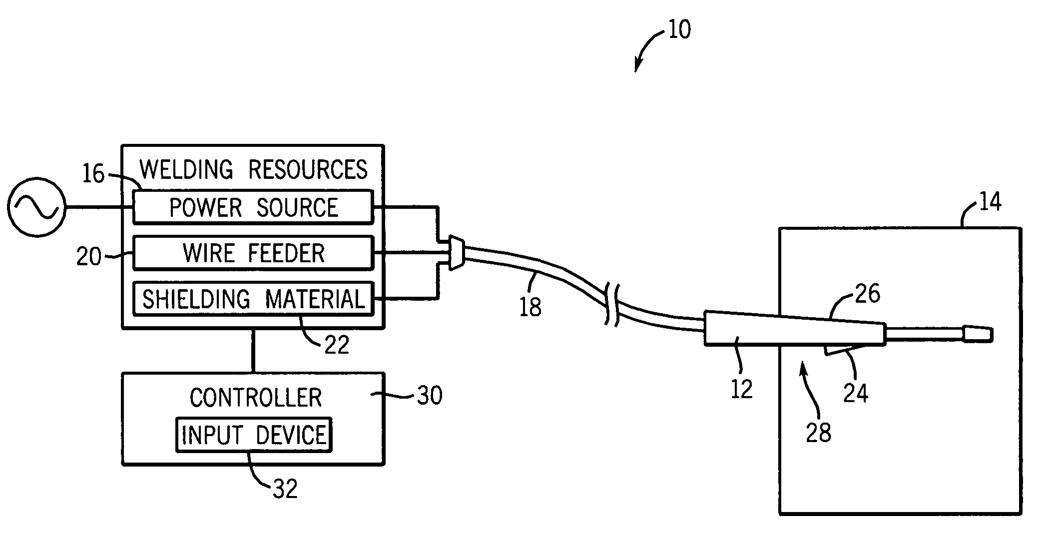
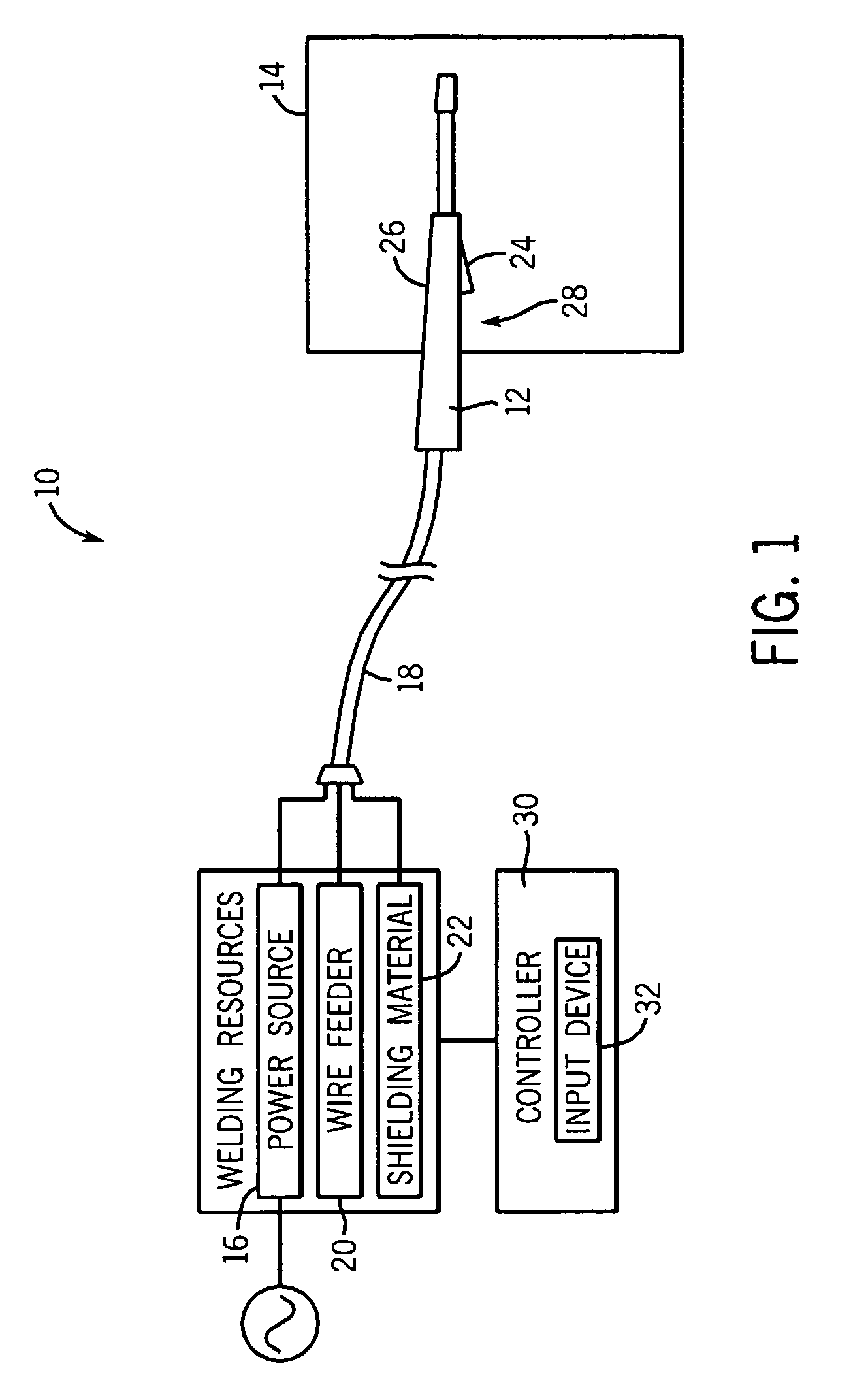
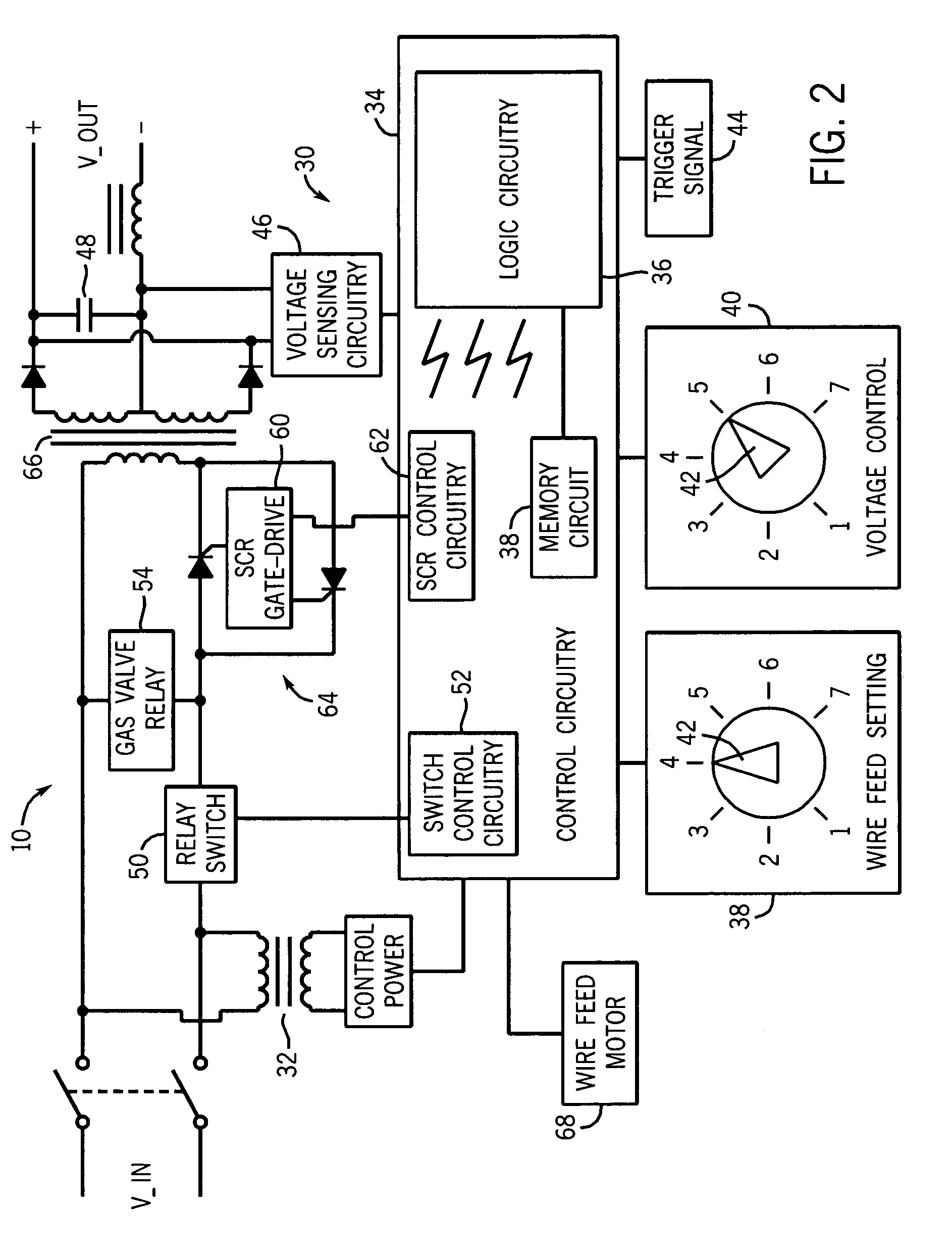
[0017]As discussed in detail below, the present technique, in accordance with certain embodiments, provides a method and apparatus for controlling a wire feed welding device. For example, a MIG welding system incorporating the present technique can be operated such that the system operates under the direction of a predetermined SCR gating (i.e., firing) scheme during start-up of the system. Thus, in such a system, arc starting is improved, as variance of the SCR firing angle is limited during arc initiation. As discussed below, the voltage applied to the welding torch and wire is essentially controlled in an open-loop manner during an initial or arc initiation period, followed by closed-loop control of voltage thereafter. The transition to and from the open-loop phase of operation may be managed in various ways to further improve operation. The resulting operation of the system has been found to be much smoother, stable and predictable, particularly during arc initiation than in con...


PUM

PropertyMeasurementUnit
voltageaaaaaaaaaa
timeaaaaaaaaaa
output voltageaaaaaaaaaa

Abstract

A system for controlling a welding operation provides for open-loop control of voltage applied to a wire electrode during an initial arc initiation stage of operation. The voltage may be based upon an operator set voltage. Electrode wire feed speeds may be varied during the same period. The voltage may be changed, but still open-loop controlled after initial contact between the electrode and a workpiece. The control transitions from open-loop to closed loop following the arc initiation stage, which may be a fixed interval or varied based upon various factors. Closed-loop voltage control then ensues, in which voltage may be limited to values based upon the initial open-loop voltage. The voltage may be regulated by control of SCR firing angles, such as by reference to a zero-crossing of an input AC waveform.

Description

BACKGROUND[0001]The present invention relates generally to wire-feed welding devices and to methods and apparatus for controlling such wire-feed welding devices.[0002]A common metal welding technique employs the heat generated by electrical arcing to transition a workpiece to a molten state, followed by addition of metal from a wire or electrode. One technique that employs this arcing principle is wire-feed welding. At its essence, wire-feed welding involves routing welding current from a power source into an electrode that is brought into close proximity with the workpiece. When the electrode contacts the work piece, current flows, and an arc is established from the electrode to the workpiece, completing a circuit and generating sufficient heat to melt and weld the workpiece. Often, the electrode is consumed and becomes part of the weld itself. Thus, new wire electrode is advanced, continuously replacing the consumed electrode and maintaining the welding arc. If the welding device ...

Claims


Application Information

Patent Timeline
Patent Type & Authority Patents(United States)
IPC IPC(8): B23K9/10B23K9/067
CPCB23K9/0672
Inventor VOGEL, BERNARD J.STANZEL, KENNETH A.
Owner ILLINOIS TOOL WORKS INC
Why Eureka
Try Eureka