Hidden multi-band window antenna

a multi-band window antenna and hidden technology, applied in the field of vehicle antennas, can solve the problems of relatively low resistance loss and poor antenna performance, and achieve the effects of effective giving a capacitive voltage feed, enhancing bandwidth, and reducing resistance loss

Active Publication Date: 2019-10-17
PITTSBURGH GLASS WORKS
View PDF34 Cites 5 Cited by
  • Summary
  • Abstract
  • Description
  • Claims
  • Application Information

AI Technical Summary

Benefits of technology

[0011]The slot antenna can be excited by a voltage source such as a balanced parallel transmission line that is connected to the opposite edges of the slot or by a coaxial transmission line that is connected to the opposite edges of the slot. The slot antenna may also be fed by a coplanar line probe. Here the inner conductor is extended along the center of the slot forming a coplanar transmission line, effectively giving a capacitive voltage feed. The antenna has a plurality antenna feeds electrically coupled to the slot at multiple positions where each position excites at least one mode of the slot. The antenna feed positions and the combination of feeds to the antenna are selected to provide a diversity antenna system with enhanced bandwidth and that meets wireless communication requirements.
[0012]The IR reflective coatings have one or more layers of silver and typically have a sheet resistance of about 3 Ω / □ for an optical transmission of about 75%. Electrical currents that flow on the coating surface result in resistance losses that impair antenna performance. To increase antenna efficiency, a bus bar such as silver or copper is printed onto the surface of the glazing near the edge of the slot antenna and is electrically connected to the conductive IR coating. The electrical conductivity of the bus bar is high relative to the conductive coating such that the slot antenna is defined by the edge of the conductive coating, the bus bar and the edge of the window frame. Most of the electrical current flows and concentrates on the high conductive bus bar so that resistance loss is relatively low. The increased conductivity in the current flow path also increases antenna radiation efficiency.
[0013]The coplanar line feed method not only provides a convenient antenna feed at any point around the perimeter of the window slot, but also affords opportunity for combination of feeds for wideband or multiple band applications. Each mode of the slot has a different field distribution with maxim points at different locations. A circuit of combined feeds can excite multiple modes of a single antenna to either improve the bandwidth or afford multiband applications. When combining two feed lines of different modes together, both signals are in phase so that they do not tend to cancel each other and, in addition, provide minimal loading to other modes. Two different feeding techniques are described in detail.

Problems solved by technology

Electrical currents that flow on the coating surface result in resistance losses that impair antenna performance.
Most of the electrical current flows and concentrates on the high conductive bus bar so that resistance loss is relatively low.

Method used


Image

  • Hidden multi-band window antenna
  • Hidden multi-band window antenna
  • Hidden multi-band window antenna

Examples


Embodiment Construction

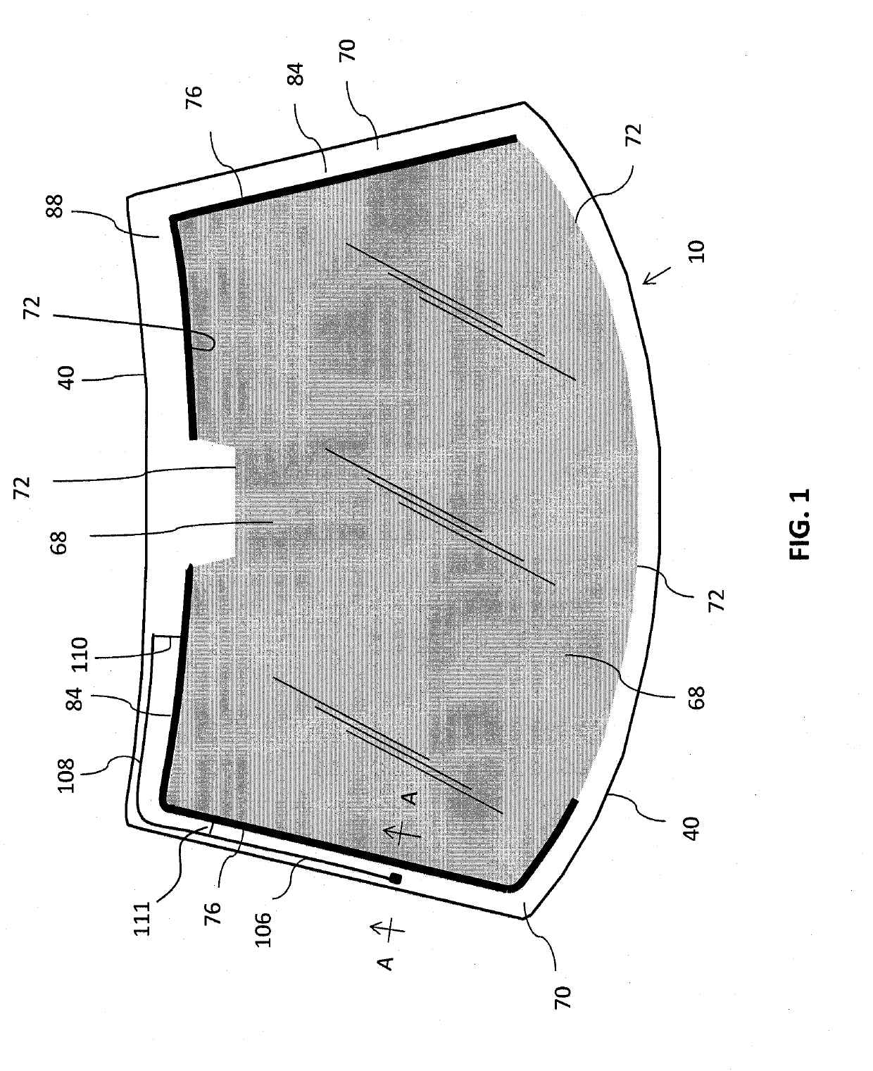
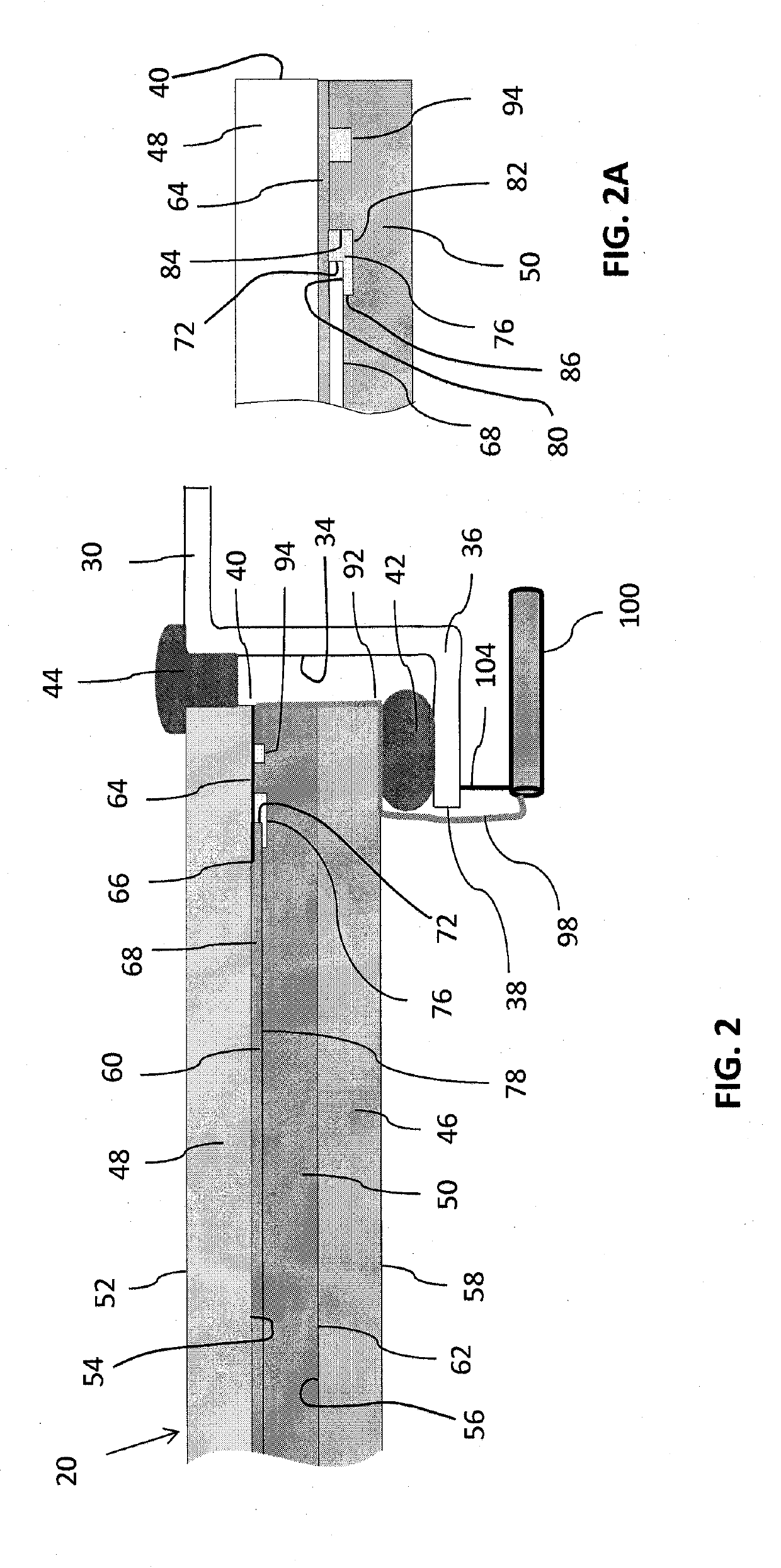
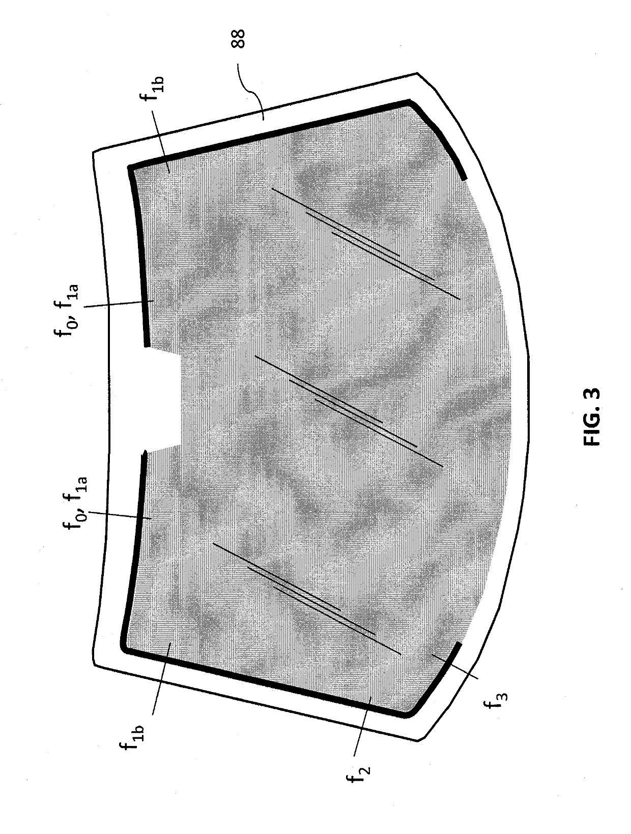
[0023]FIGS. 1 and 2 disclose an antenna windshield 10 for use in a vehicle, including associated structure that incorporates features of the presently disclosed invention. In FIGS. 1 and 2, a glazing 20 is surrounded by a metal frame 30 of a vehicle body. Frame 30 defines a surface 34 that forms a portal for receiving glazing 20. The portal surface 34 includes the surface of an annular flange 36 that has an edge 38. Glazing 20 defines an outer perimeter edge 40 that overlaps annular flange 36. As particularly shown in FIG. 2, an annular seal 42 is located between perimeter edge 40 of window glazing 20 and annular flange 36. A molding 44 bridges an outer gap between annular flange 36 and glazing 20.

[0024]In the embodiment of FIGS. 1 and 2, glazing 20 is a laminated glazing that includes inner transparent ply 46 and outer transparent ply 48 that may be composed of glass. Inner ply 46 and outer ply 48 are bonded together by an interlayer layer 50. Preferably, interlayer 50 is made of a...


PUM


Abstract

A slot antenna in a vehicle glazing established between the surface of the vehicle portal for the glazing and the peripheral edge of an IR reflective coating that has a bus bar over the coating edge. The antenna slot is fed directly by a voltage probe and/or a conductive line located in the slot and parallel to the bus bar. Multiple voltage probes and conductive lines can support respective antennas. A second conductive line is parallel and cooperates with the first conductive line to form a coupled coplanar line that links to the antenna slot. The longitudinal location of the links and the length of the coplanar lines are adjusted to excite multiple frequency modes. Multiple antennas can be used to broaden overall bandwidth or to add additional frequency modes.

Description

TECHNICAL FIELDField of the Invention[0001]The present invention relates generally to vehicle antennas and, more particularly, to antennas formed in association with a glazing having an electrically conductive coating.BACKGROUND OF THE INVENTIONDiscussion of the Prior Art[0002]In the prior art, as an alternative to standard whip antennas and roof mount mast antennas, automotive antennas have been concealed in the glazing. In some cases, such antennas have been made by silver printing techniques. More recently, embedded wire antennas of quarter or half wavelength have been used in laminated windshields and back windows. In such glazings, a wire is embedded in an interlayer of polyvinyl butyral that is sandwiched between a pair of glass sheets.[0003]Many wire antenna designs known in the prior art have located the antenna wire in the daylight opening of the windshield or glass window for better performance. In the case of a convertible vehicle, the back window is movable and therefore...

Claims


Application Information

Patent Timeline
Patent Type & Authority Applications(United States)
IPC IPC(8): H01Q1/12H01Q13/10
CPCH01Q1/1271H01Q13/10H01Q21/28H01Q5/35
Inventor DAI, DAVID
Owner PITTSBURGH GLASS WORKS
Why Eureka
Try Eureka