Electronic device and method for verifying correct program execution

a technology of electronic devices and program execution, applied in error detection/correction, redundant data error correction, instruments, etc., can solve problems such as program execution, error detection code values determined, and errors occurred

Active Publication Date: 2014-11-18
TEXAS INSTR INC
View PDF8 Cites 2 Cited by
  • Summary
  • Abstract
  • Description
  • Claims
  • Application Information

AI Technical Summary

Benefits of technology

[0007]In one aspect of the invention, an electronic device is provided which comprises a microprocessor for executing a program code. There is further a first hardware code path verifying (CPV) stage coupled to the microprocessor. The first hardware CPV stage comprises a first error detection code (EDC) generator. The first EDC generator is configured to continuously determine an error detection code on a continuous sequence of code relating to an actually executed portion of the program code. The first hardware CPV stage is configured to compare the actual error detection code with a predetermined error code so as to verify correct execution of the program code. Based on the comparison result the CPV stage can indicate an error or abnormal program code execution. In this aspect of the invention, the CPV stage can be implemented in hardware and independently and separately from the microprocessor. Furthermore, the CPV stage includes an EDC generator, which may for example be a stage for performing a cyclic redundancy check (CRC). The EDC generator can receive code that relates to the program which is actually executed. The program code or related data is fed as a continuous sequence of data to the EDC generator, which continuously calculates error detection code values on the received data. “Continuous” means that the data or code is forwarded to the CPV stage and / or EDC generator and processed in the EDC generator when it occurs during program execution and not only at certain breakpoints. Forwarding and processing of data and / or code to the EDC generator or CPV stage may be performed based on a clock signal and in accordance with the steps of executing the program. However, the comparison of the determined error detection code values may only be performed at some breakpoints of the program. This means that the CPV stage provides highest granularity and therefore highest safety standards. Furthermore, the CPV stage does not consume additional data processing time from the microprocessor.
[0017]In still another aspect of the invention, there may also be more than one CPV stage. In an embodiment, there may be a second hardware CPV stage and the first hardware CPV stage and the second hardware CPV stage may be configured to be independently enabled or disabled. Similar to using several EDC generators within one CPV it can be useful to use various CPV stages and / or EDC generators. The CPV stages and / or EDC generators may then be configured to be enabled or disabled when the program enters or leaves loops within the program flow. This can be a very efficient way of verifying code independent of the number of loops or the number of times a program goes through a loop. In an embodiment, the electronic device may be configured to use two hardware CPV stages or two EDC generators in order to handle the loops of a program. A first hardware CPV stage or EDC generator may then be enabled when the loop is entered and a second CPV stage or EDC generator may be disabled. When the loop is left, the second CPV stage or EDC generator may be enabled and the first hardware CPV stage or EDC generator may then be disabled. Two or more CPV stages may be used if two or more busses or other hardware structures or components are to be monitored independently.

Problems solved by technology

However, the comparison of the determined error detection code values may only be performed at some breakpoints of the program.
If the values do not match, an error has occurred at some point during the program execution.
However, a parity bit is an error detection mechanism that can only detect an odd number of errors.

Method used


Image

  • Electronic device and method for verifying correct program execution
  • Electronic device and method for verifying correct program execution
  • Electronic device and method for verifying correct program execution

Examples


Embodiment Construction

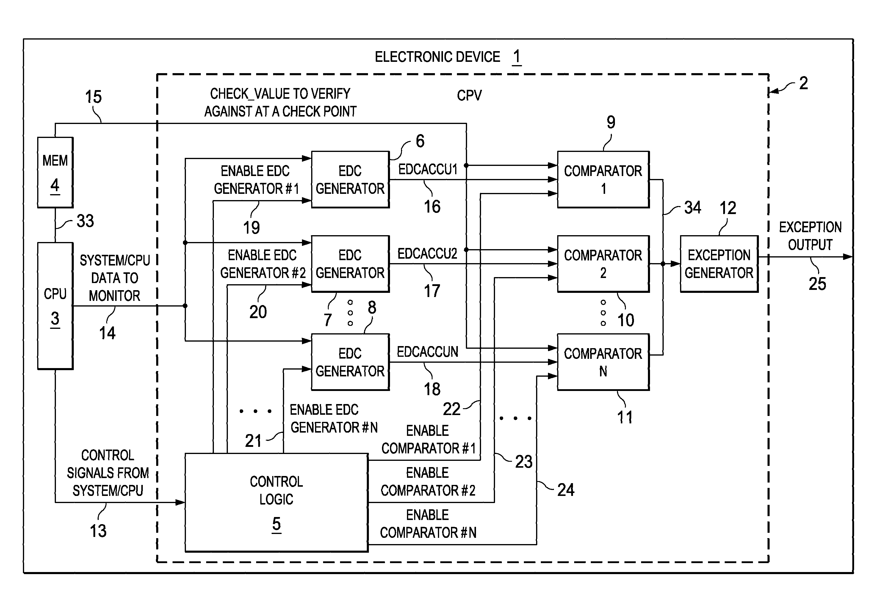
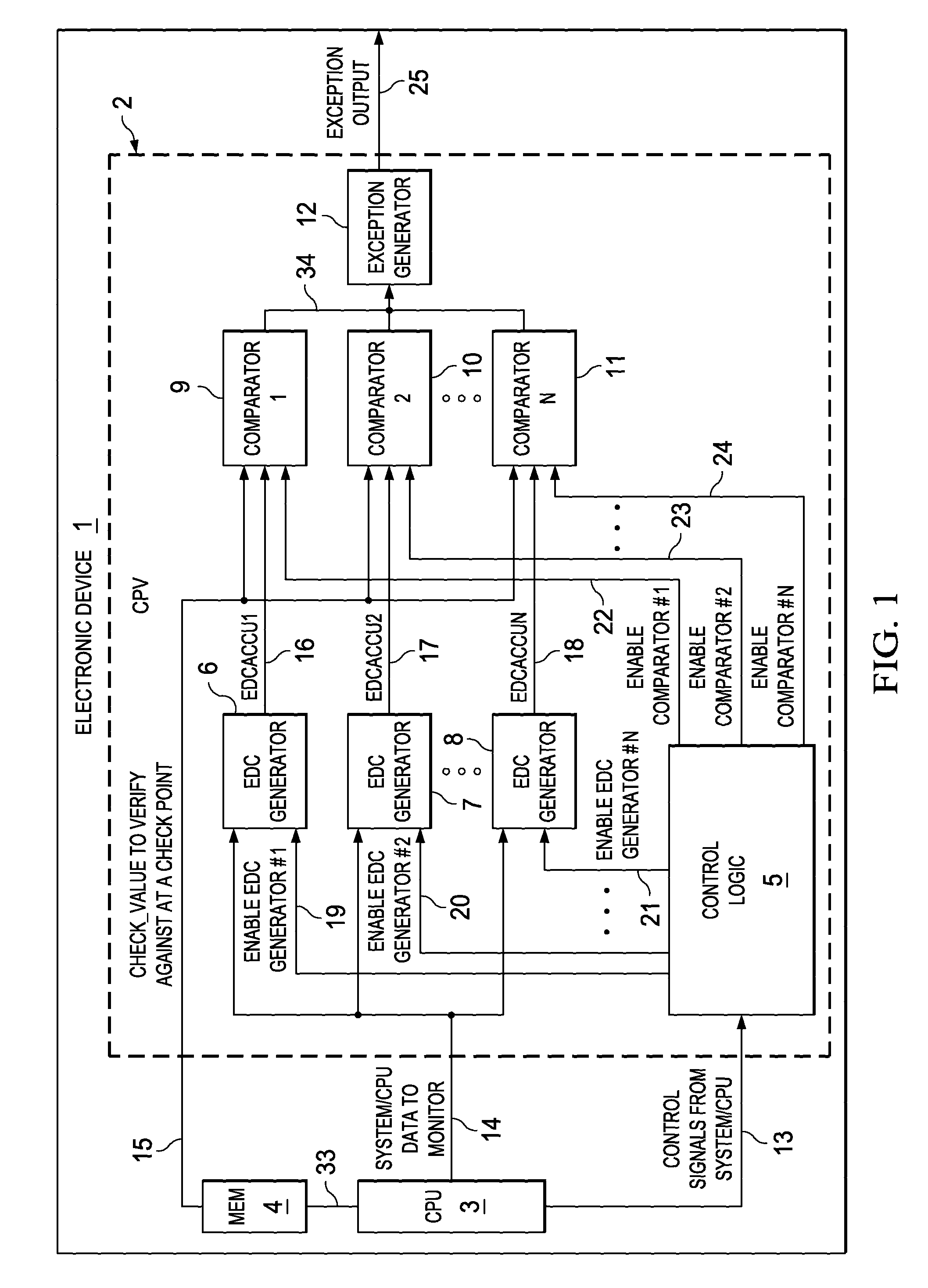
[0027]FIG. 1 shows a simplified block diagram of an electronic device 1 according to aspects of the invention. The electronic device 1 may be a microprocessor or microcontroller embedded system. The electronic device 1 may completely be integrated as an integrated semiconductor device or some components, as for example the microprocessor (or microcontroller) CPU 3, the memory 4 and the CPV stage 2 may be integrated on a single or multiple semiconductor dice. According to aspects of the invention, the microprocessor CPU 3 is supplemented by a CPV stage 2. The CPV stage 2 may be connected to a microprocessor input / output (I / O) port (as shown) but it may also be arranged inside the microprocessor 3. The CPV stage can be configured to monitor any code or data relating to program execution, as for example the program code, any address data, and internal, deterministic CPU state data or any other data the CPU is processing. There may be two or more EDC generators inside a CPV stage which ...


PUM


Abstract

An electronic device is provided which comprises a microprocessor for executing a program code and a first hardware code path verifying (CPV) stage coupled to the microprocessor. The hardware CPV stage comprises a first error detection code (EDC) generator configured to continuously determine an error detection code on a continuous sequence of code relating to an actually executed portion of the program code and to compare the actual error detection code with a predetermined error code so as to verify correct execution of the program code and to indicate an error.

Description

CROSS-REFERENCE TO RELATED APPLICATIONS[0001]This patent application claims priority from German Patent Application No. 10 2009 037 630.5, filed Aug. 14, 2009, which is incorporated herein by reference in its entirety.FIELD OF THE INVENTION[0002]The present invention relates to an electronic device including a microprocessor for executing a program code configured to verify correct execution of the program code and a corresponding method.BACKGROUND OF THE INVENTION[0003]Microprocessor based systems or embedded microcontroller systems, as for example passive or active entry systems, RFID systems, smart and security cards require safe and reliable program execution. Harsh or extreme operating conditions as well as malicious fault attacks can cause malfunctioning and unsafe operation, which is to be avoided under all circumstances.[0004]In order to detect errors and deviations from normal program execution, it is known in the art to insert some checkpoints into the program code. At the...

Claims


Application Information

Patent Timeline
Patent Type & Authority Patents(United States)
IPC IPC(8): G06F11/10G06F11/00
CPCG06F11/1048
Inventor INGIMUNDARSON, ARNI
Owner TEXAS INSTR INC
Why Eureka
Try Eureka