Projectile

a projectile and projectile technology, applied in the field of projectiles, can solve the problems of lack of superior ballistic performance and stability of the projectile, lack of cavity in the center of the projectile coupled with the specific, etc., and achieve the effect of superior flight stability characteristics

Active Publication Date: 2014-11-25
ESCOBAR ROLANDO
View PDF40 Cites 203 Cited by
  • Summary
  • Abstract
  • Description
  • Claims
  • Application Information

AI Technical Summary

Benefits of technology

[0009]It is one of the main objects of the present invention to prov

Problems solved by technology

None of them, however, includes a cavity in the center of the projectile coupled with the specific proportions of the various aspects of the present

Method used


Image

  • Projectile
  • Projectile
  • Projectile

Examples


Embodiment Construction

[0019]Projectiles, also sometimes referred to as bullets in small arms, is generally any object that is forced from the barrel of a gun under pressure. These projectiles can range from a pellet (or BB) gun powered by compressed air, a spring, or other similar means to battlefield artillery that may have a bore diameter of thirty centimeters or more.

[0020]Since about the middle of the 19th century, rifling in gun barrels has become commonplace. Rifling is a precise feature of the interior of a gun barrel that imparts a rotation upon the projectile as it travels through the barrel. The rotation of the projection aids in a true flight path of the projectile and therefore increasing the ability of the shooter to hit a selected target.

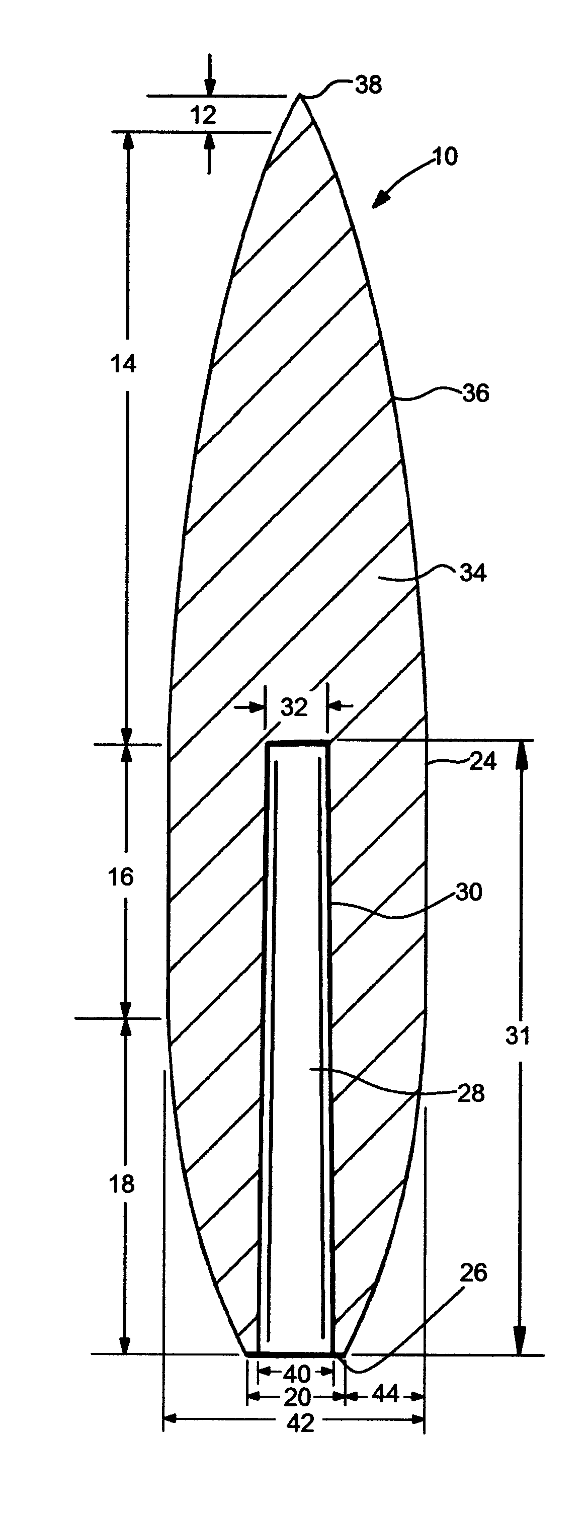
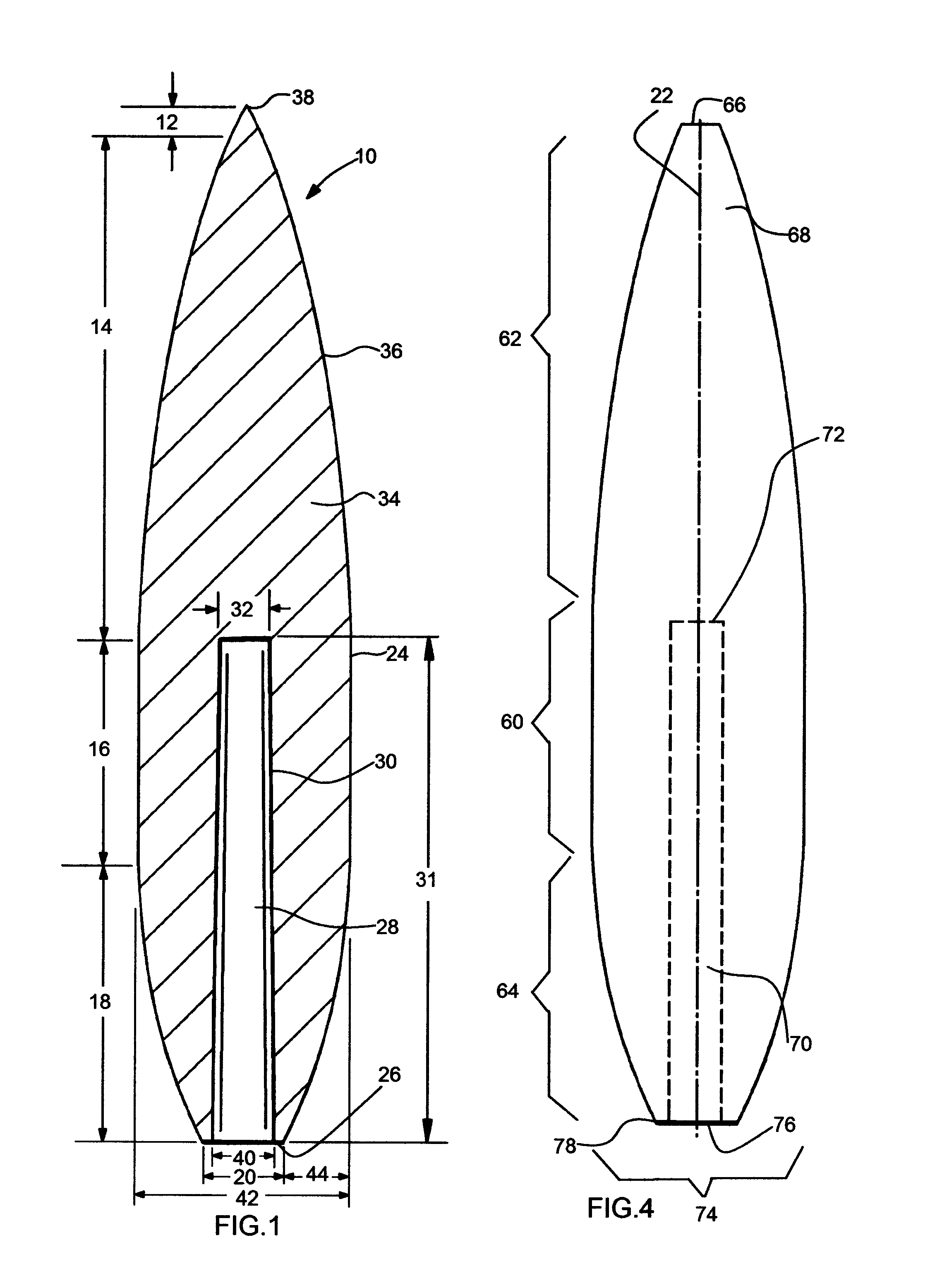
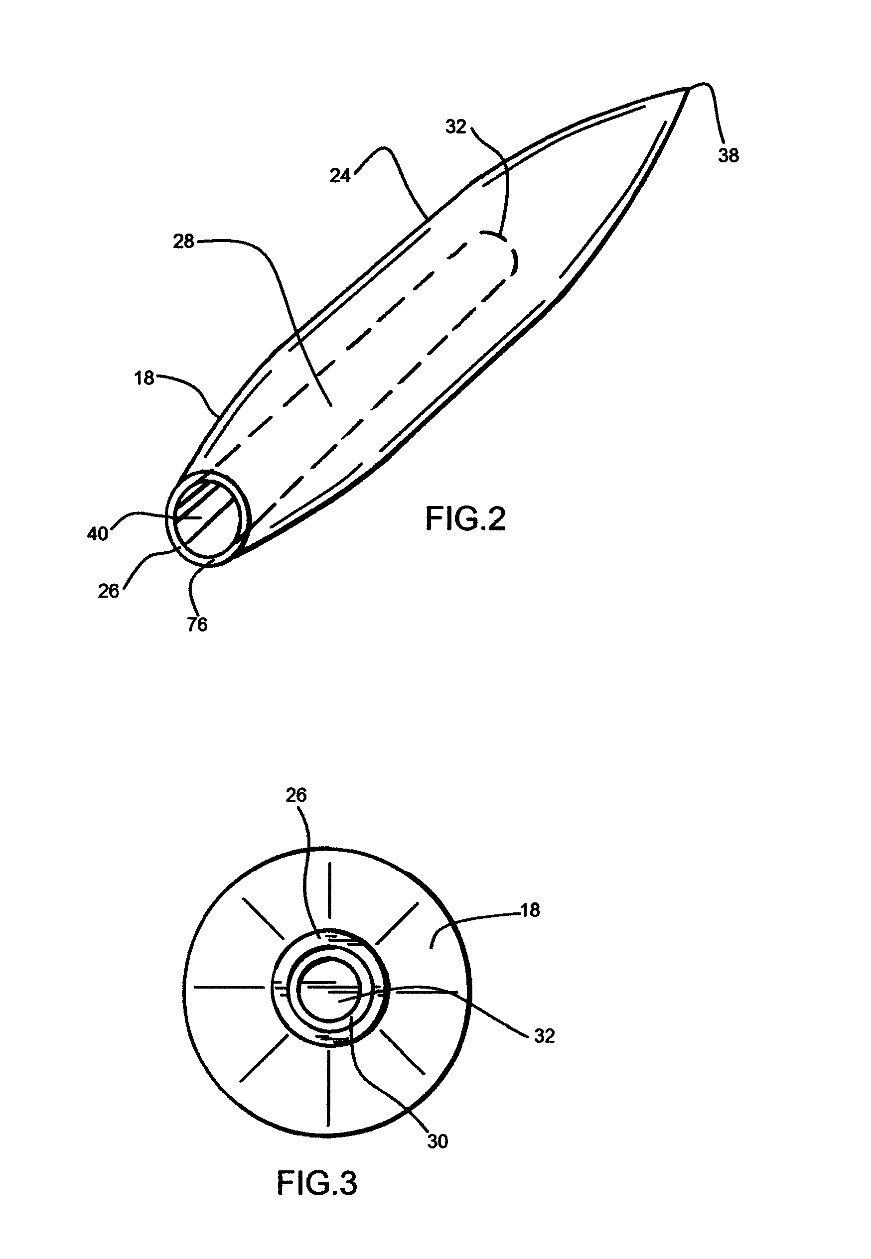
[0021]Referring now to the drawings, where an important version of the present invention is generally referred to with numeral 10 in FIG. 1. It can be observed in the drawings that this version of the invention basically includes a nose 12, an ogive 14, a b...


PUM


Abstract

A projectile comprised of an ogive section, a bearing surface section and a boattail section. A cavity is formed inside the projectile from an aperture on the aft end of the boattail section and forward to about the transition point (shoulder) between the ogive section and bearing surface section. The cavity is centered about the centerline of the projectile and open on the aft end of the projectile.

Description

BACKGROUND OF THE INVENTION[0001]1. Field of the Invention[0002]The present invention relates to projectiles, and more particularly, to projectiles for air guns, firearms and other small arms.[0003]2. Description of the Related Art[0004]Several designs for projectiles have been designed in the past. None of them, however, includes a cavity in the center of the projectile coupled with the specific proportions of the various aspects of the presently disclosed device.[0005]Applicant believes that the closest reference corresponds to U.S. Pat. No. 8,186,277 issued to King on 29 May 2012. However, it differs from the present invention, because among other reasons, the King device has a cavity on the forward edge of his projectile that is deformable upon impact with no analogous cavity in the rear side of the projectile as shown and described in the present invention.[0006]The present invention, in at least one important version, includes no cavity at the tip of the projectile and instead...

Claims


Application Information

Patent Timeline
IPC IPC(8): F42B10/44
CPCF42B10/44
Inventor ESCOBAR, ROLANDO
Owner ESCOBAR ROLANDO
Why Eureka
Try Eureka