Hydraulic system with fluid flow summation control of a variable displacement pump and priority allocation of fluid flow

a variable displacement pump and fluid flow technology, applied in fluid couplings, clutches, servomotors, etc., can solve the problems of low performance of other hydraulic functions and loss of efficiency of previous flow priority techniques

Inactive Publication Date: 2014-12-02
HUSCO INT INC
View PDF26 Cites 11 Cited by
  • Summary
  • Abstract
  • Description
  • Claims
  • Application Information

AI Technical Summary

Benefits of technology

[0017]When only the second hydraulic function is operating, fluid from the pump passes freely from the flow summation node through the third path of the control valve in the first hydraulic function and into the bypass passage. The third path of the control valve in the second hydraulic function now is reduced in size restricting flow farther to the return conduit. As a result, fluid flows from the bypass passage through a first priority check valve to the second supply node, where that fluid is available relatively unrestricted to power the hydraulic actuator in the second hydraulic function.

Problems solved by technology

Thus it is necessary to ensure that the demands for supply fluid of the higher priority functions are met to the greatest possible degree, even if doing so results in lower performance of other hydraulic functions.
Previous flow priority techniques often had losses in efficiency, such as heat losses.

Method used


Image

  • Hydraulic system with fluid flow summation control of a variable displacement pump and priority allocation of fluid flow
  • Hydraulic system with fluid flow summation control of a variable displacement pump and priority allocation of fluid flow
  • Hydraulic system with fluid flow summation control of a variable displacement pump and priority allocation of fluid flow

Examples


Embodiment Construction

[0024]The term “directly connected” and “directly connects” as used herein means that the associated components are connected together by a conduit without any intervening element, such as a valve, an orifice or other device, which restricts or controls the flow of fluid beyond the inherent restriction of any conduit. If a component is described as being “directly connected” between two points or hydraulic circuit nodes, that component is directly connected to each such point or node.

[0025]Although the present invention is being described in the context of use on an earth excavator, it can be implemented on other hydraulically operated machines.

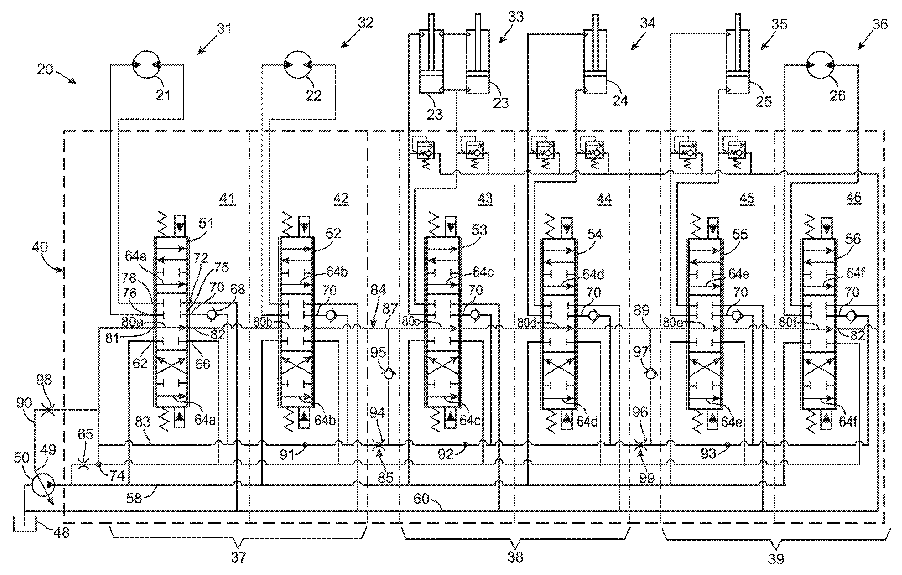
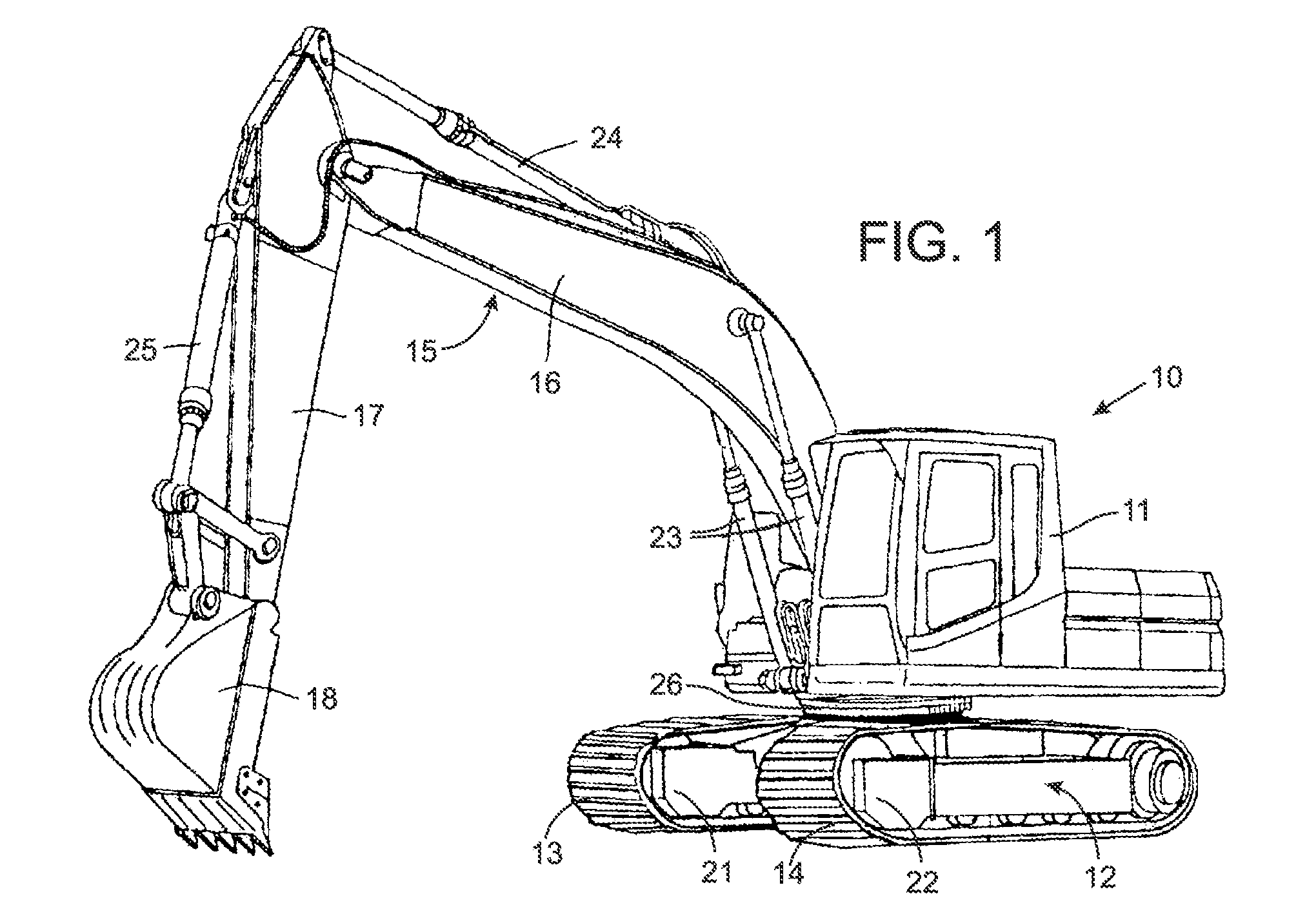
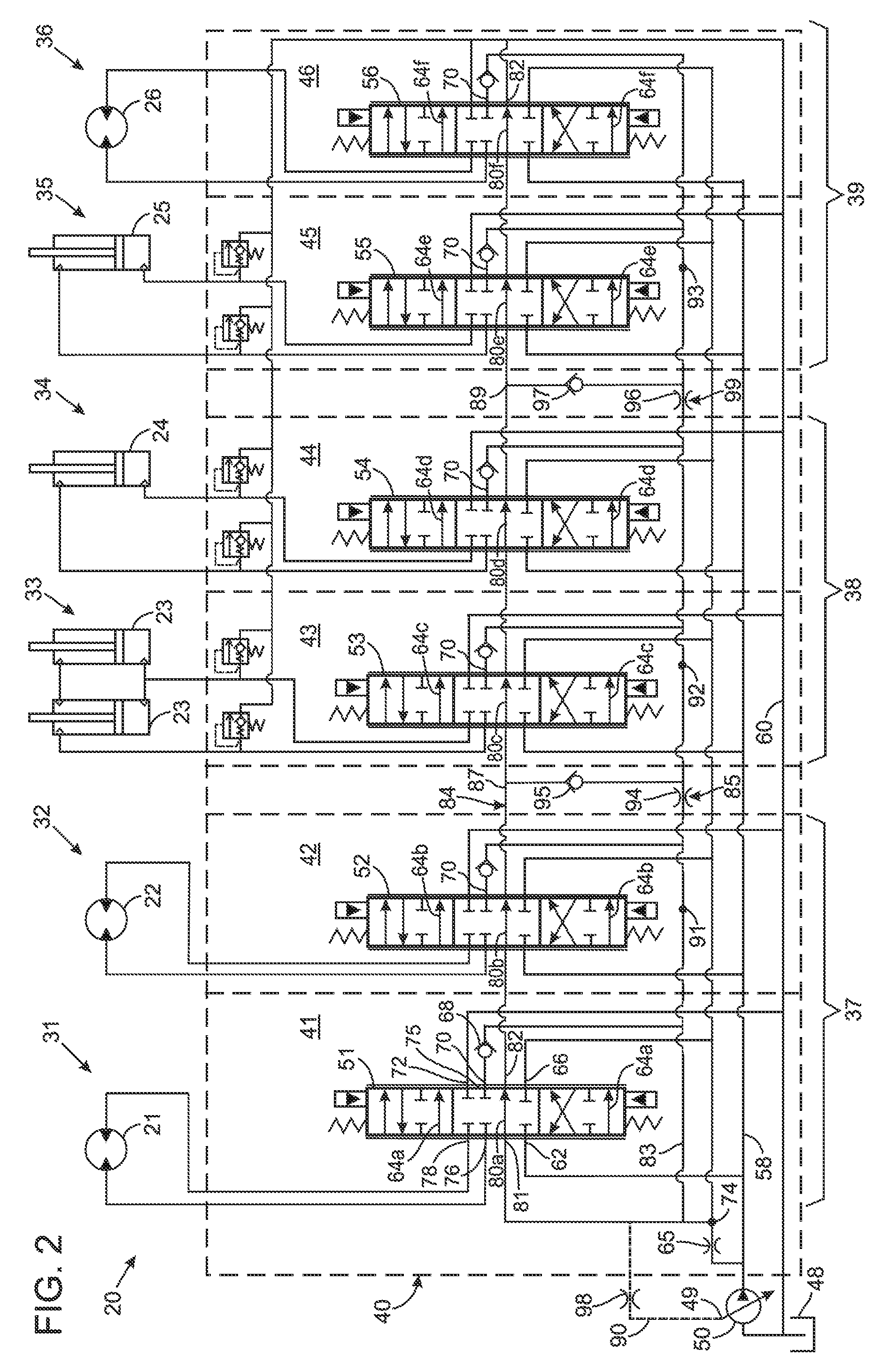
[0026]With initial reference to FIG. 1, an excavator 10 comprises a cab 11 that can swing clockwise and counter-clockwise on a crawler 12 when driven by a hydraulic motor 26. The crawler 12 is propelled by right and left tracks 13 and 14 that are driven by separate hydraulic motors 21 and 22, respectively.

[0027]A boom assembly 15, attached to...


PUM


Abstract

A system has a variable displacement pump that supplies pressurized fluid to power a plurality of hydraulic functions. Each hydraulic function has a control valve with a variable source orifice controlling fluid flow between the pump and a flow summation node, and a variable metering orifice controlling fluid flow between the flow summation node and a hydraulic actuator. Variable bypass orifices in the control valves are connected in series between the flow summation node and a tank. As the metering orifice in a control valve enlarges, the source orifice enlarges and the bypass orifice shrinks. This alters pressure at the flow summation node, which is used to control the output of the pump. Components are provided to give selected hydraulic functions different levels of priority with respect to consuming fluid flow from the pump.

Description

CROSS-REFERENCE TO RELATED APPLICATIONS[0001]Not ApplicableSTATEMENT REGARDING FEDERALLY SPONSORED RESEARCH OR DEVELOPMENT[0002]Not ApplicableBACKGROUND OF THE INVENTION[0003]1. Field of the Invention[0004]The present invention relates to valve assemblies for operating hydraulically powered machinery; and more particularly to such valve assemblies that produce a pressure signal which controls a variable displacement hydraulic pump and that give priority to the use of fluid from the pump to operate selected hydraulic actuators.[0005]2. Description of the Related Art[0006]The speed of a hydraulically driven working member on a machine depends upon the cross-sectional area of principal narrowed orifices of the hydraulic system and the pressure drop across those orifices. To facilitate control, pressure compensating hydraulic control systems have been designed to manage the pressure drop. These previous control systems include load sense conduits which transmit the pressure at the valve...

Claims


Application Information

Patent Timeline
Patent Type & Authority Patents(United States)
IPC IPC(8): F16D31/02
CPCF15B11/162F15B2211/7142F15B2211/40507F15B2211/3122F15B2211/455F15B2211/351F15B2211/41509F15B2211/40515F15B2211/781F15B2211/3116F15B11/17
Inventor BALLWEG, JACOBPIEPER, GARY J.QUINNELL, COREY K.STARKEY, JONATHAN M.HAMKINS, ERIC P.
Owner HUSCO INT INC
Why Eureka
Try Eureka