
Liquid-ejecting head and liquid-ejecting apparatus

a liquid ejector and liquid ejector technology, which is applied in the direction of printing, inking apparatus, etc., can solve the problems of inability to prevent the viscosity of ink feed to the vicinity of the nozzle opening immediately before being ejected as an ink droplet from being problematically increased, and the quality of liquid ejecting cannot be uniformly maintained. to achieve the effect of enhancing the quality of liquid ejector

Active Publication Date: 2014-12-02
SEIKO EPSON CORP
View PDF19 Cites 14 Cited by
  • Summary
  • Abstract
  • Description
  • Claims
  • Application Information

AI Technical Summary

Benefits of technology

The invention provides a liquid-ejecting head and apparatus that can prevent the liquid from becoming too viscous and from depositing components. This results in improved quality of liquid ejection.

Problems solved by technology

Variation is therefore caused in quality of ejection of an ink droplet with the passage of time, and the quality of ink ejection cannot be accordingly uniformly maintained.
In addition, components contained in ink precipitate with the result that difference is generated between components contained in a continuously ejected ink droplet and components contained in an intermittently ejected ink droplet.
Even in the case where the ink stored in the common liquid chamber, which is in communication with a plurality of the pressure-generating chambers in common, is circulated as described in JP-A-2009-247938 and Japanese Patent No. 3161095, unfortunately, the viscosity of ink which has been fed to the vicinity of the nozzle opening immediately before being ejected as an ink droplet cannot be prevented from being problematically increased, and deposition of components contained in the ink cannot be sufficiently suppressed.
The quality of liquid ejection is therefore disadvantageously decreased.
Such disadvantages arise not only in the ink jet recording head from which ink is ejected but in a liquid-ejecting head from which liquids other than the ink are ejected.

Method used


Image

  • Liquid-ejecting head and liquid-ejecting apparatus
  • Liquid-ejecting head and liquid-ejecting apparatus
  • Liquid-ejecting head and liquid-ejecting apparatus

Examples


first embodiment

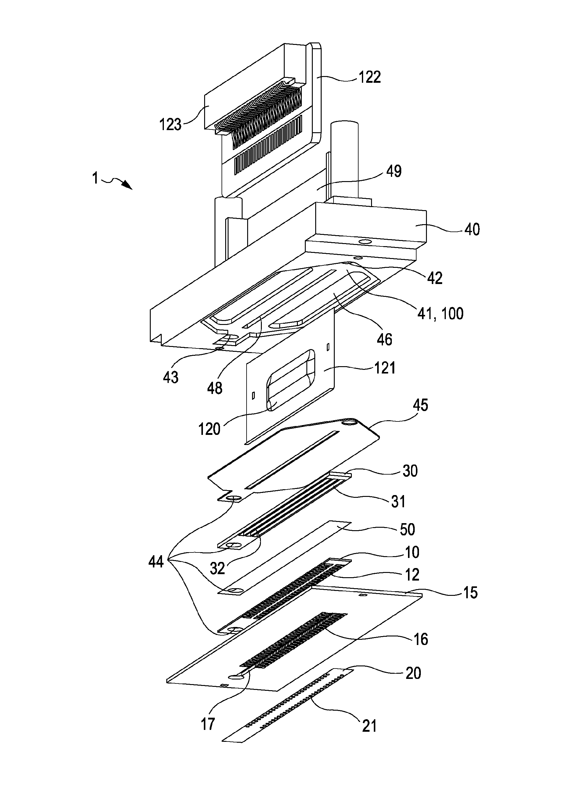
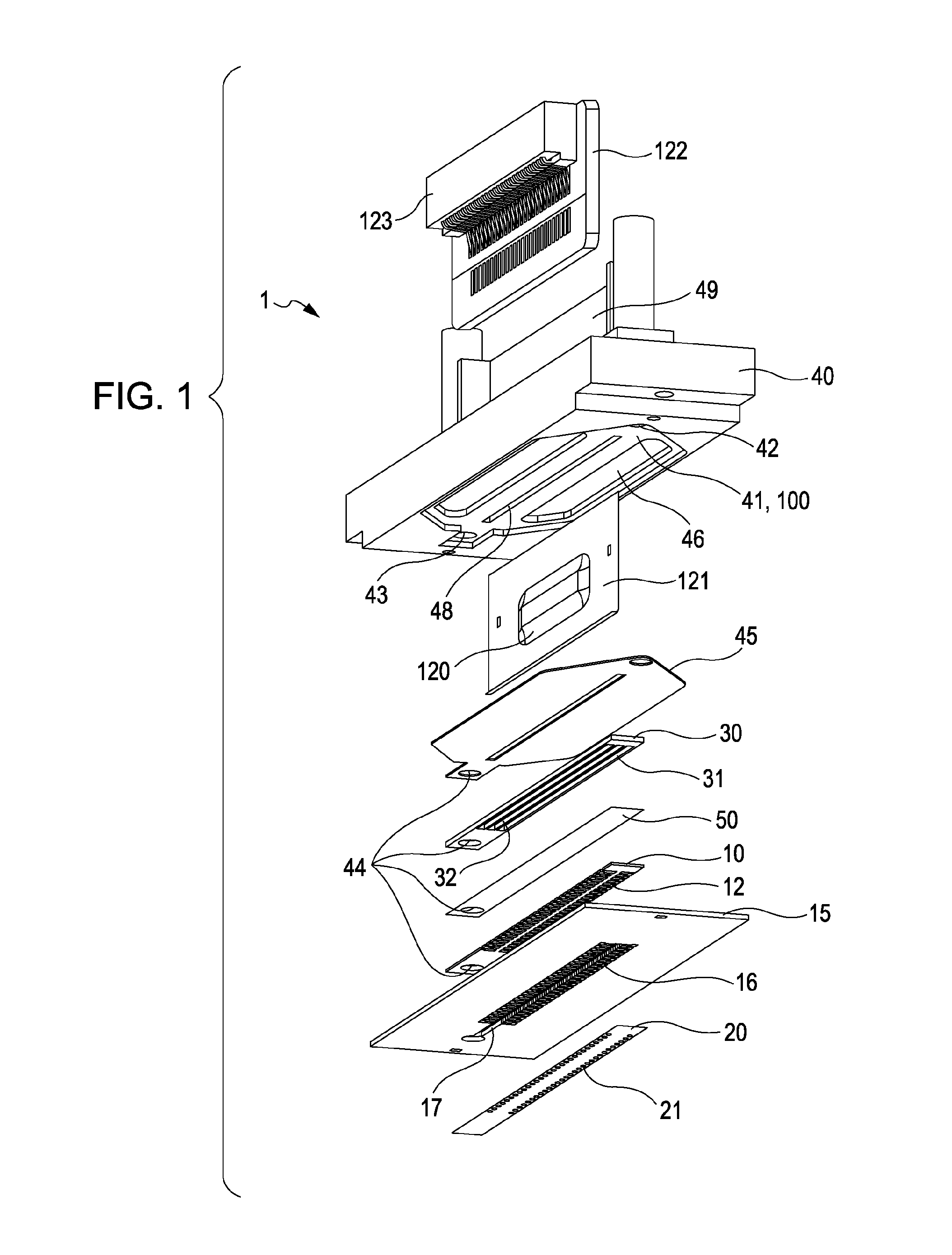
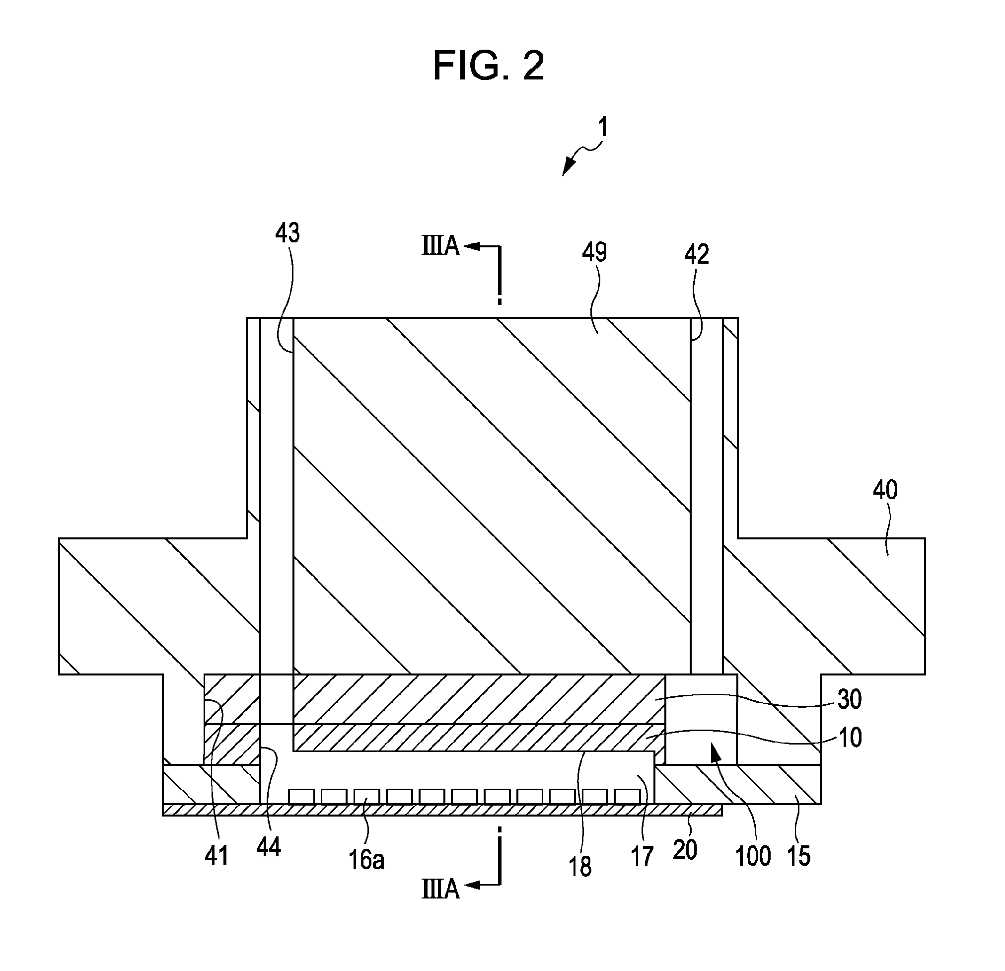
[0037]FIG. 1 is an exploded perspective view illustrating an ink jet recording head as an example of a liquid-ejecting head of the first embodiment of the invention. FIG. 2 is a cross-sectional view illustrating the ink jet recording head in the lateral direction of a pressure-generating chamber. FIG. 3A is a cross-sectional view illustrating the ink jet recording head taken along a line IIIA-IIIA in FIG. 2, and FIG. 3B is a cross-sectional view partially illustrating the ink jet recording head in FIG. 3A in an enlarged manner. FIG. 4 is a cross-sectional view illustrating a channel configuration.

[0038]In this embodiment, a silicon single-crystal substrate having a (110) orientation is used to form a channel-forming substrate 10, and an elastic film 50 that is made by using silicon dioxide is provided on one surface of the channel-forming substrate 10 as illustrated in the drawings. The channel-forming substrate 10 has two lines individually including a plurality of pressure-generat...

second embodiment

[0064]FIG. 5 is a cross-sectional view illustrating an ink jet recording head as an example of a liquid-ejecting head of a second embodiment of the invention. In this embodiment, the components the same as those in the first embodiment are denoted by the same symbols, and similar description is omitted.

[0065]With reference to FIG. 5, an ink jet recording head 1A of this embodiment includes the channel-forming substrate 10 on which the piezoelectric actuators 300 are formed, the nozzle plate 20 having the nozzle openings 21, a communication plate 15A provided between the channel-forming substrate 10 and nozzle plate 20, the protection substrate 30, and the case 40.

[0066]The communication plate 15A is provided between the channel-forming substrate 10 and the nozzle plate 20 and is formed as a result of stacking a second communication plate 152 and a first communication plate 151 in sequence from the nozzle plate 20 to the channel-forming substrate 10.

[0067]The communication plate 15A ...

third embodiment

[0072]FIG. 6 is a cross-sectional view illustrating a channel configuration of a third embodiment. FIG. 7 is a perspective view partially illustrating a circulation channel in an enlarged manner. FIG. 8 is a plan view partially illustrating the circulation channel in an enlarged manner. In this embodiment, the components the same as those in the first embodiment are denoted by the same symbols, and similar description is omitted.

[0073]As illustrated in the drawings, an ink jet recording head 1B of this embodiment has a configuration the same as that in the first embodiment except that narrow portions 200 are formed at part of the circulation channel 17A.

[0074]In particular, a plurality of the narrow portions 200 are provided on the downstream side (side of the discharging channel 43) relative to a region in which the circulation channel 17A is in communication with the individual circulation communication channels 16a, and two narrow portions 200 are provided in this embodiment.

[007...


PUM


Abstract

A liquid-ejecting head includes a nozzle plate having a nozzle opening that serves for liquid ejection; a channel-forming substrate including pressure-generating chambers that are in communication with the nozzle opening; a pressure generator that serves to generate pressure change in a liquid in the pressure-generating chambers; and a communication plate provided between the nozzle plate and the channel-forming substrate, the communication plate having a communication channel that forms a communication between the pressure-generating chambers and the nozzle opening. The communication plate has a circulation channel that is in communication with a common liquid chamber through the communication channel, the common liquid chamber being in communication with a plurality of the pressure-generating chambers in common.

Description

[0001]This application claims a priority to Japanese Patent Application No. 2011-003490 filed on Jan. 11, 2011 which is hereby expressly incorporated by reference herein in its entirety.BACKGROUND[0002]1. Technical Field[0003]The present invention relates to a liquid-ejecting head having a nozzle opening from which a liquid is ejected and relates to a liquid-ejecting apparatus. The invention especially relates to an ink jet recording head and ink jet recording apparatus in which ink is ejected as the liquid.[0004]2. Related Art[0005]An ink jet recording head is one of typical examples of a liquid-ejecting head from which an ink droplet are ejected. Examples of the ink jet recording head include a recording head which includes a channel-forming substrate having a pressure-generating chamber and a piezoelectric actuator provided on one surface of the channel-forming substrate. In such a recording head, the piezoelectric actuator is deformed to apply pressure to the inside of the press...

Claims


Application Information

Patent Timeline
Patent Type & Authority Patents(United States)
IPC IPC(8): B41J2/14
CPCB41J2202/12B41J2002/14491B41J2/14233
Inventor AKAHANE, FUJIOTAKAHASHI, TOMOAKI
Owner SEIKO EPSON CORP
Learn More