
Methods and systems for air fuel ratio control

a technology of air fuel ratio and air fuel ratio, which is applied in the direction of machines/engines, propulsion parts, process and machine control, etc., can solve the problems of increased nitrogen oxide (nosub>x/sub>) emissions, increased particulate matter emissions, and increased fuel consumption, so as to improve engine performance and reduce emissions. , the effect of air fuel ratio

Active Publication Date: 2014-12-02
GE GLOBAL SOURCING LLC
View PDF33 Cites 3 Cited by
  • Summary
  • Abstract
  • Description
  • Claims
  • Application Information

AI Technical Summary

Benefits of technology

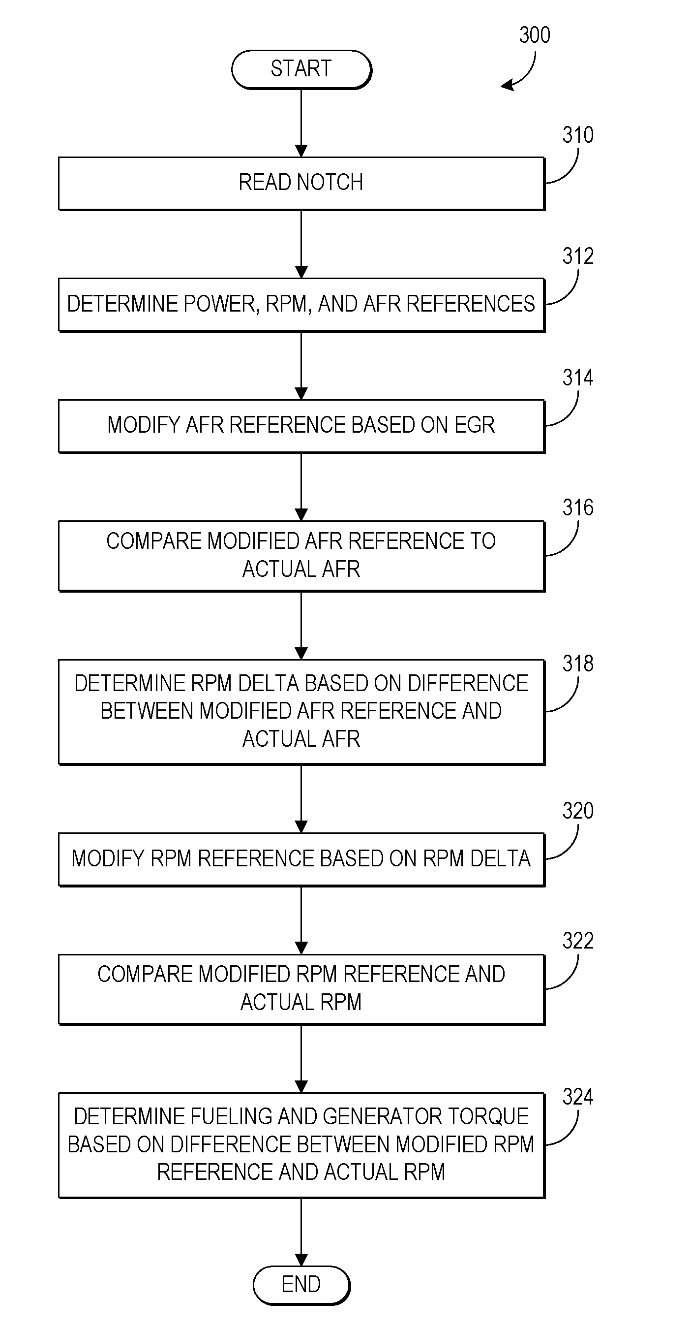
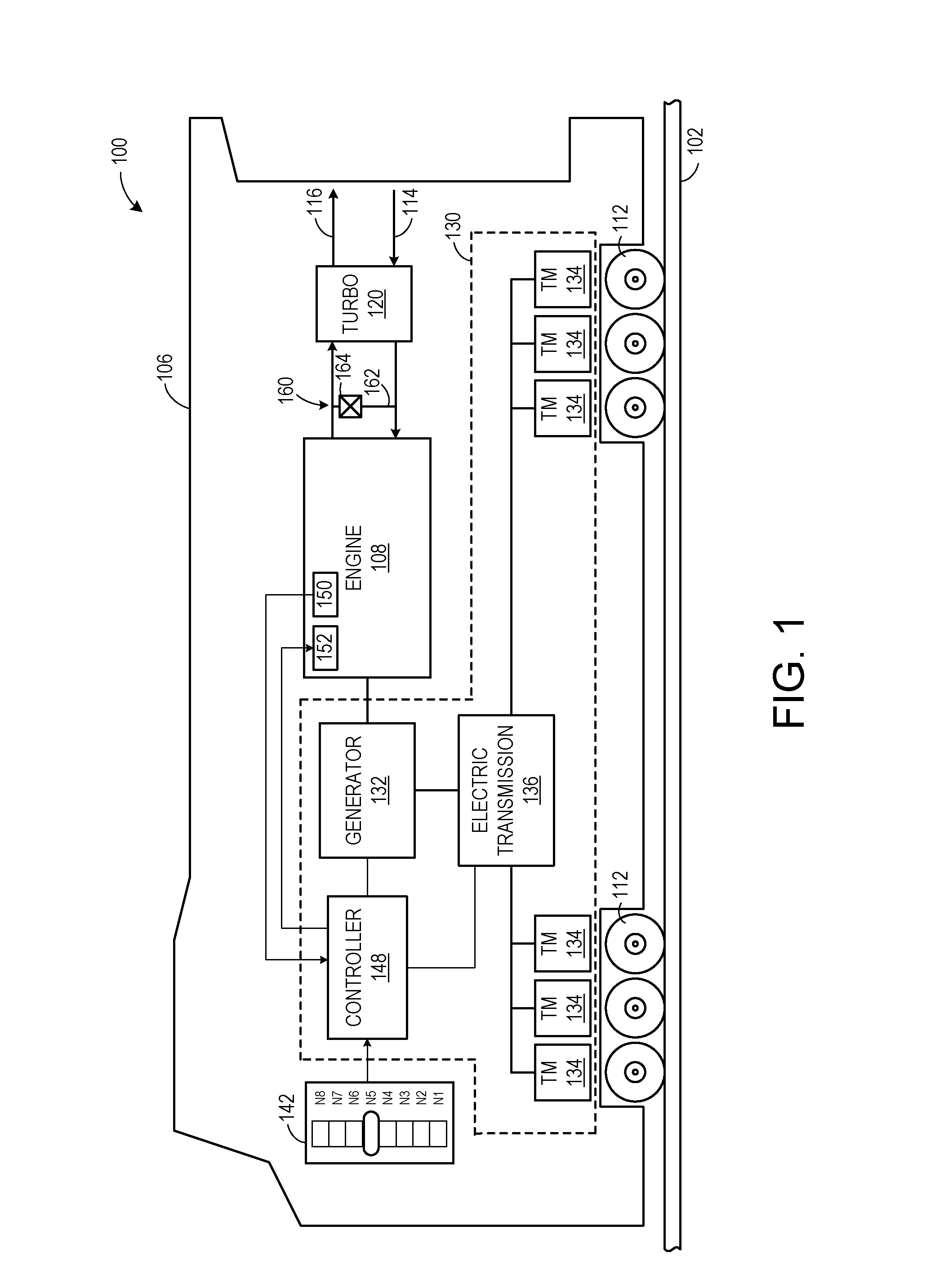
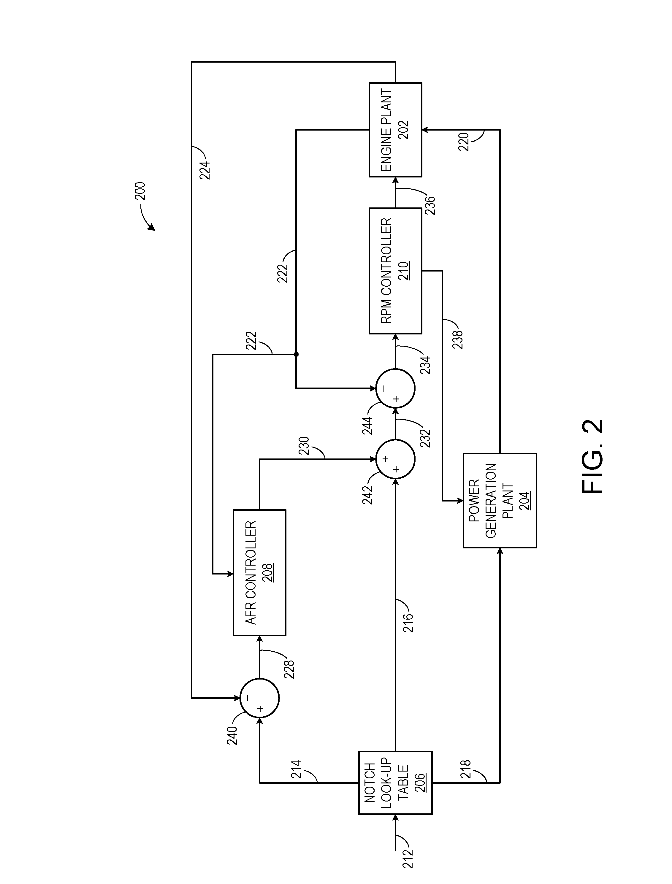
[0004]In one embodiment, a method for an engine driving an electrical power generation system includes adjusting an engine speed in response to a relationship between oxygen and fuel while maintaining a power transmitted to the electrical power generation system. By maintaining the power transmitted to the electrical power generation system, a vehicle speed may be maintained, for the example where the engine is included in a propulsion system of a vehicle. Further, changing the ratio of engine speed to vehicle speed while maintaining the vehicle speed and power may result in a proportional effect on the relationship between oxygen and fuel, such as engine air fuel ratio or oxygen-to-fuel ratio. As such, the air fuel ratio may be controlled without changing the boost provided by a turbocharger, or in addition to changing the boost if desired. In this manner, engine performance may be maintained while decreasing emissions.

Problems solved by technology

Under some conditions, an overly low air fuel ratio may result in increased particulate matter emissions, while an overly high air fuel ratio may result in increased nitrogen oxide (NOx) emissions and higher fuel consumption due to increased pumping losses.
By adjusting the boost, however, the engine power output may be affected, even when there is no command to change the engine power.
As such, while air fuel ratio control may be improved, overall engine output control may degrade.

Method used


Image

  • Methods and systems for air fuel ratio control
  • Methods and systems for air fuel ratio control
  • Methods and systems for air fuel ratio control

Examples


Embodiment Construction

[0010]The following description relates to various embodiments of methods and systems for an engine driving an electrical power generation system. In one example method, an engine speed is adjusted in response to an air fuel ratio (e.g., a difference between an actual / current air fuel ratio and a desired air fuel ratio of the engine, as determined by or derived from sensor data or otherwise) while a power transmitted by the engine to the electrical power generation system is maintained. As will be described in greater detail below, engine speed may be adjusted by adjusting fueling and adjusting generator torque, for example. In this manner, the power transmitted by the engine to the electrical power generation system may be maintained such that a vehicle speed may be maintained. Further, changing the engine speed to vehicle speed ratio by changing the engine speed and maintaining the vehicle speed and power may proportionally affect engine speed and inversely affect engine torque, r...


PUM


Abstract

Various methods and systems for an engine driving an electrical power generation system are provided. In one embodiment, an example method for an engine driving an electrical power generation system includes adjusting an engine speed in response to a relationship between oxygen and fuel while maintaining a power transmitted to the electrical power generation system.

Description

FIELD[0001]Embodiments of the subject matter disclosed herein relate to methods and systems for controlling air fuel ratio in an internal combustion engine.BACKGROUND[0002]Combustion in an engine, such as an internal combustion engine, occurs with an amount of fuel and an amount of air present in a cylinder of the engine. The ratio of the amount of air to the amount of fuel is known as the air fuel ratio. Under some conditions, an overly low air fuel ratio may result in increased particulate matter emissions, while an overly high air fuel ratio may result in increased nitrogen oxide (NOx) emissions and higher fuel consumption due to increased pumping losses.[0003]In some approaches, the air fuel ratio may be adjusted by controlling a wastegate on a turbocharger or controlling a variable geometry turbocharger. In this manner, an amount of boost provided by the turbocharger may be adjusted, thereby changing an amount of air available for combustion in the cylinder. By adjusting the bo...

Claims


Application Information

Patent Timeline
Patent Type & Authority Patents(United States)
IPC IPC(8): F02D41/00F02M25/07F02D29/06F02D31/00F02D41/14F02D41/10
CPCF02D41/107F02D2041/1419F02D41/0072F02D41/0007F02D29/06F02D2250/32F02M25/0709F02M25/0707F02D31/007Y02T10/47F02D41/1454F02D41/04F02M26/05F02M26/06Y02T10/12Y02T10/40
Inventor MISCHLER, JAMES ROBERTFRITZ, JASSIN MARCELFREUND, SEBASTIAN WALTER
Owner GE GLOBAL SOURCING LLC
Learn More