
Air-fuel ratio control apparatus and method for internal combustion engine

Inactive Publication Date: 2001-10-09
TOYOTA JIDOSHA KK
View PDF4 Cites 3 Cited by
  • Summary
  • Abstract
  • Description
  • Claims
  • Application Information

AI Technical Summary

Benefits of technology

Therefore, the difference between the torque produced during the fuel concentration-increasing control (that is, the air-fuel ratio-decreasing control) and the torque produced during the fuel concentration-decreasing control (that is, the air-fuel ratio-increasing control) becomes smaller. Hence, the torque fluctuation caused by the air-fuel ratio control of the internal combustion engine can be reduced, and the drivability can be improved.
Thus, the sixth aspect of the invention achieves advantages similar to those of the second aspect. Furthermore, the sixth aspect of the invention is able to realize an air-fuel ratio control apparatus similar to that of the second aspect by using process contents of an air-fuel ratio feedback system that are based on the air-fuel ratio feedback control that uses increasing and decreasing of the amount of fuel supplied while minimizing the changes needed in programs. Thus, the costs needed for changes in programs can be minimized

Problems solved by technology

However, the above-described air-fuel ratio feedback control technologies have a problem of fluctuation of torque produced by the internal combustion engine.
Therefore, in either one of the air-fuel ratio feedback control technologies, the drivability becomes insufficient in some cases.
Therefore, while the control system is performing the intake air-increasing process based on the air-fuel ratio feedback adjustment coefficient, the amount of fuel supplied to the internal combustion engine is not affected by increases in the amount of intake air, and therefore is not substantially adjusted by the air-fuel ratio feedback control.
Therefore, while the control system is performing the intake air-decreasing process based on the air-fuel ratio feedback adjustment coefficient, the amount of supplied fuel set by the control system is not affected by decreases in the amount of intake air to the internal combustion engine, and therefore is not substantially adjusted by the air-fuel ratio feedback control.

Method used


Image

  • Air-fuel ratio control apparatus and method for internal combustion engine
  • Air-fuel ratio control apparatus and method for internal combustion engine
  • Air-fuel ratio control apparatus and method for internal combustion engine

Examples


first embodiment

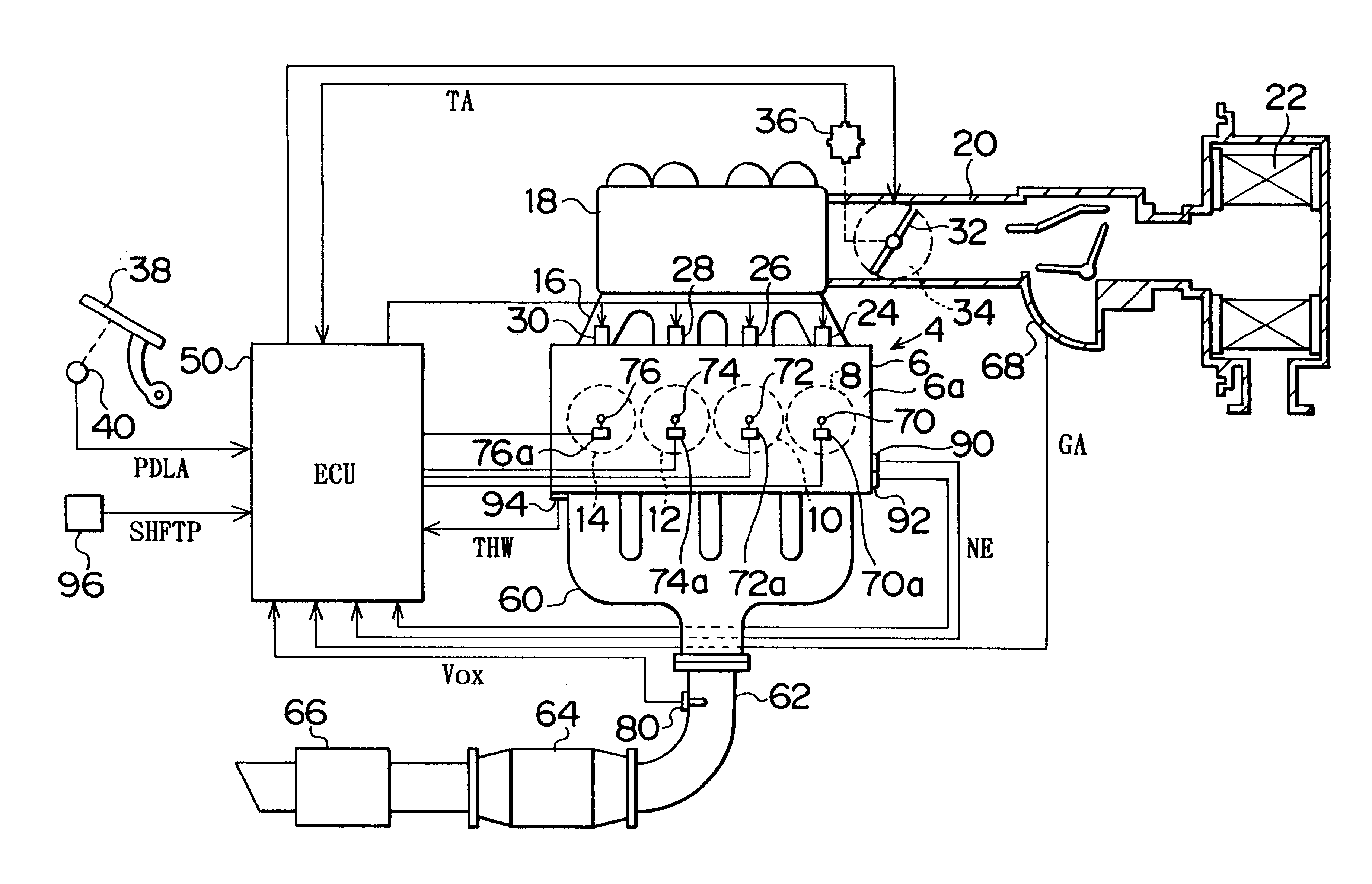
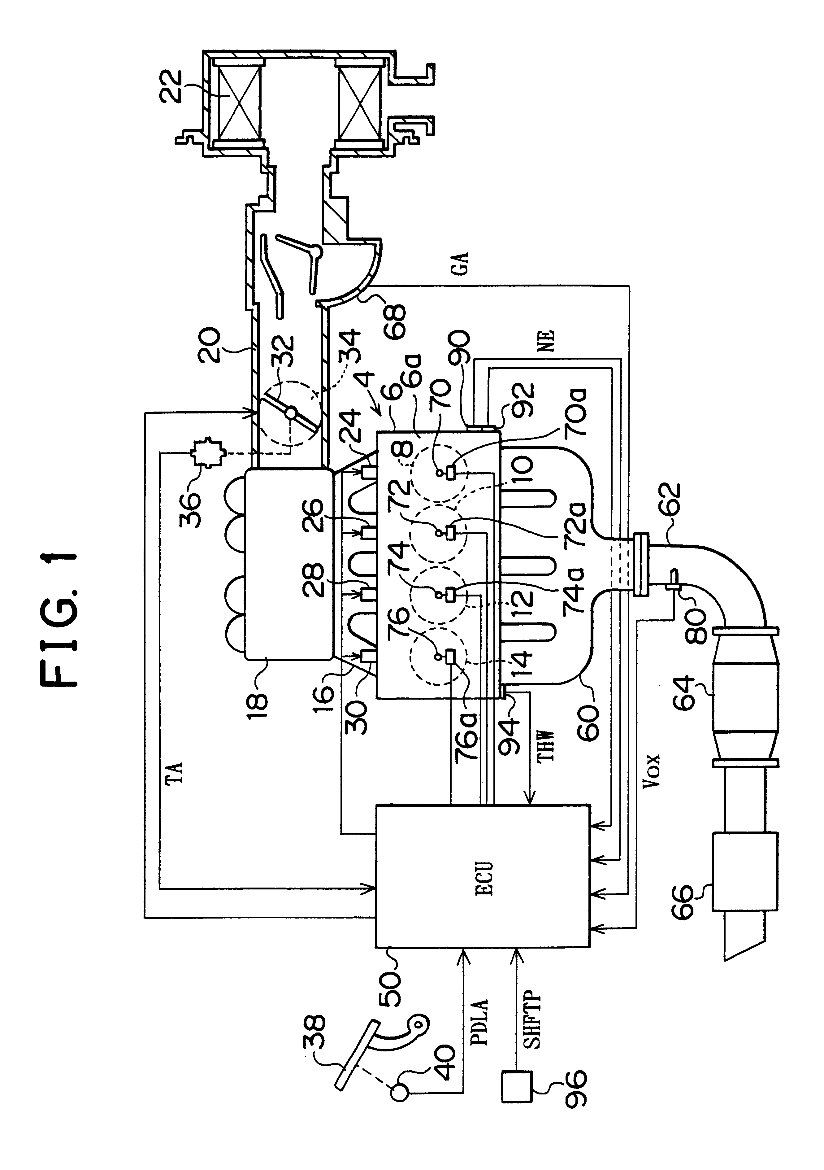
The first embodiment is based on the air-fuel ratio feedback control in which the state of air-fuel ratio is reflected in the increase or decrease of the fuel injection amount, as illustrated in FIG. 8. However, the invention is also applicable to a system that is based on an air-fuel ratio feedback control in which the state of air-fuel ratio is reflected in the increase or decrease of the intake air amount.

Moreover, although the first embodiment employs the air-fuel ratio sensor 80 capable of detecting the oxygen concentration in a broad range as an air-fuel ratio detector, the invention can also be realized by employing an oxygen sensor that is capable of detecting the oxygen concentration only in a limited range around the theoretical air-fuel ratio.

Further, while in the first embodiment the air-fuel ratio sensor 80 is disposed upstream of the catalytic converter 64, the invention is also applicable to a system in which an air-fuel ratio sensor 80 is disposed downstream of the c...


PUM


Abstract

An air-fuel ratio control apparatus performs an intake air-increasing process based on a region of an air-fuel ratio feedback adjustment coefficient FAF in which the adjustment coefficient decreases the fuel concentration in an air-fuel mixture. The apparatus calculates a fuel injection valve open duration TAU by using a newly calculated air-fuel ratio feedback adjustment coefficient FAFx, instead of using an adjustment coefficient FAF. An air-fuel ratio-increasing feedback adjustment coefficient FVLV in the adjustment coefficient FAFx has a value that cancels an increase in the amount of intake air. Therefore, the fuel injection amount is increased only when the fuel concentration in the mixture is an intake air-increasing process. Hence, torque difference between fuel concentration-increasing and concentration-decreasing control becomes smaller.

Description

INCORPORATION BY REFERENCEThe disclosure of Japanese Patent Application No. HEI 11-129792 filed on May 11, 1999 including the specification, drawings and abstract is incorporated herein by reference in its entirety.1. Field of the InventionThe present invention relates to an air-fuel ratio control apparatus and method for an internal combustion engine and, more particularly, to an air-fuel ratio control apparatus for an internal combustion engine that detects the air-fuel ratio of an air-fuel mixture supplied into the engine and performs the feedback control of the concentration of fuel in the mixture on the basis of the detected air-fuel ratio so that the air-fuel ratio becomes equal to the theoretical air-fuel ratio.2. Description of the Related ArtA technology for controlling the air-fuel ratio of air-fuel mixture to the theoretical air-fuel ratio with high precision has been developed in relation to the emission control of an internal combustion engine using a catalyst. In this ...

Claims


Application Information

Patent Timeline
IPC IPC(8): F02D41/18F02D41/14F02D41/02
CPCF02D41/1456F02D41/18
Inventor MUTO, HARUFUMIFUJITA, MAKOTOKUSHI, NAOTO
Owner TOYOTA JIDOSHA KK
Learn More