
Misfire detection device for internal combustion engine, misfire detection method for internal combustion engine, and memory medium

a technology for internal combustion engines and misfire detection devices, which is applied in the direction of electric control, machines/engines, fuel injection control, etc., can solve the problems of limiting the influence of tolerance on the rotation fluctuation amount, erroneous misfire determination, and difficulty in accurately determining whether a misfire has occurred from the above-described relative magnitud

Active Publication Date: 2022-08-04
TOYOTA JIDOSHA KK
View PDF60 Cites 0 Cited by
  • Summary
  • Abstract
  • Description
  • Claims
  • Application Information

AI Technical Summary

Benefits of technology

The described configuration in this patent allows for accurate determination of misfires in an internal combustion engine. By measuring the rotation speed of the crankshaft, misfires can be detected with high accuracy, even when the engine is running. This is achieved by measuring the rotation speed at specific angles during the compression process. The configuration also takes into account the deactivation process, which can affect the accuracy of the measurement. Overall, this configuration provides a reliable means for identifying misfires in engines.

Problems solved by technology

Thus, when, for example, the rotation fluctuation amount of the cylinder of the subject of the deactivation of the combustion control (i.e., deactivated cylinder) is used as the reference rotation fluctuation amount, it is difficult to accurately determine whether a misfire has occurred from the above-described relative magnitude.
This limits the influence of the tolerance on the rotation fluctuation amount of the subject of the determination.
However, in this case, an erroneous misfire determination is made if the rotation fluctuation amount at the previous 360° CA is calculated from the instantaneous rotation speed corresponding to the deactivated cylinder.

Method used


Image

  • Misfire detection device for internal combustion engine, misfire detection method for internal combustion engine, and memory medium
  • Misfire detection device for internal combustion engine, misfire detection method for internal combustion engine, and memory medium
  • Misfire detection device for internal combustion engine, misfire detection method for internal combustion engine, and memory medium

Examples


Embodiment Construction

[0029]This description provides a comprehensive understanding of the methods, apparatuses, and / or systems described. Modifications and equivalents of the methods, apparatuses, and / or systems described are apparent to one of ordinary skill in the art. Sequences of operations are exemplary, and may be changed as apparent to one of ordinary skill in the art, with the exception of operations necessarily occurring in a certain order. Descriptions of functions and constructions that are well known to one of ordinary skill in the art may be omitted.

[0030]Exemplary embodiments may have different forms, and are not limited to the examples described. However, the examples described are thorough and complete, and convey the full scope of the disclosure to one of ordinary skill in the art.

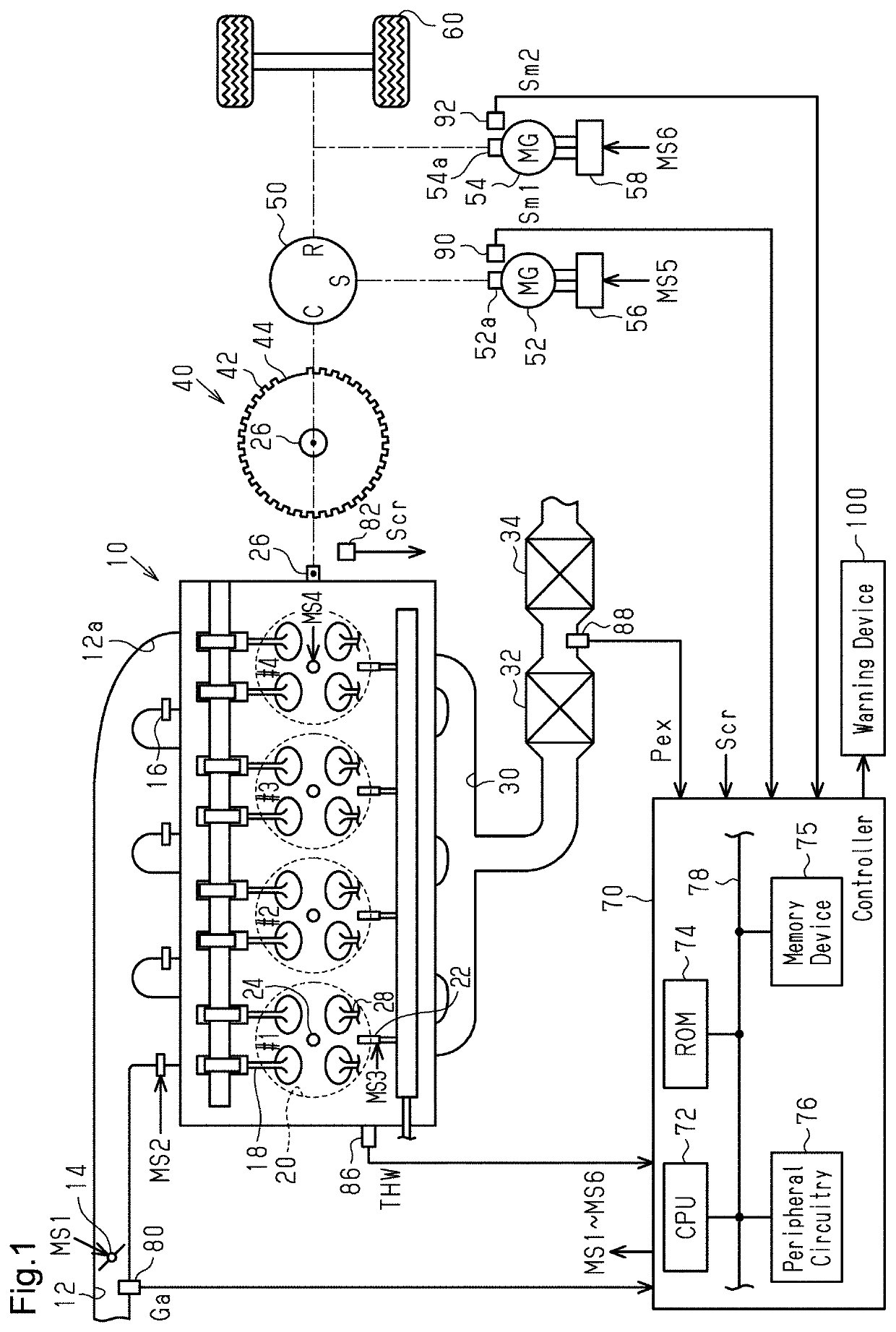
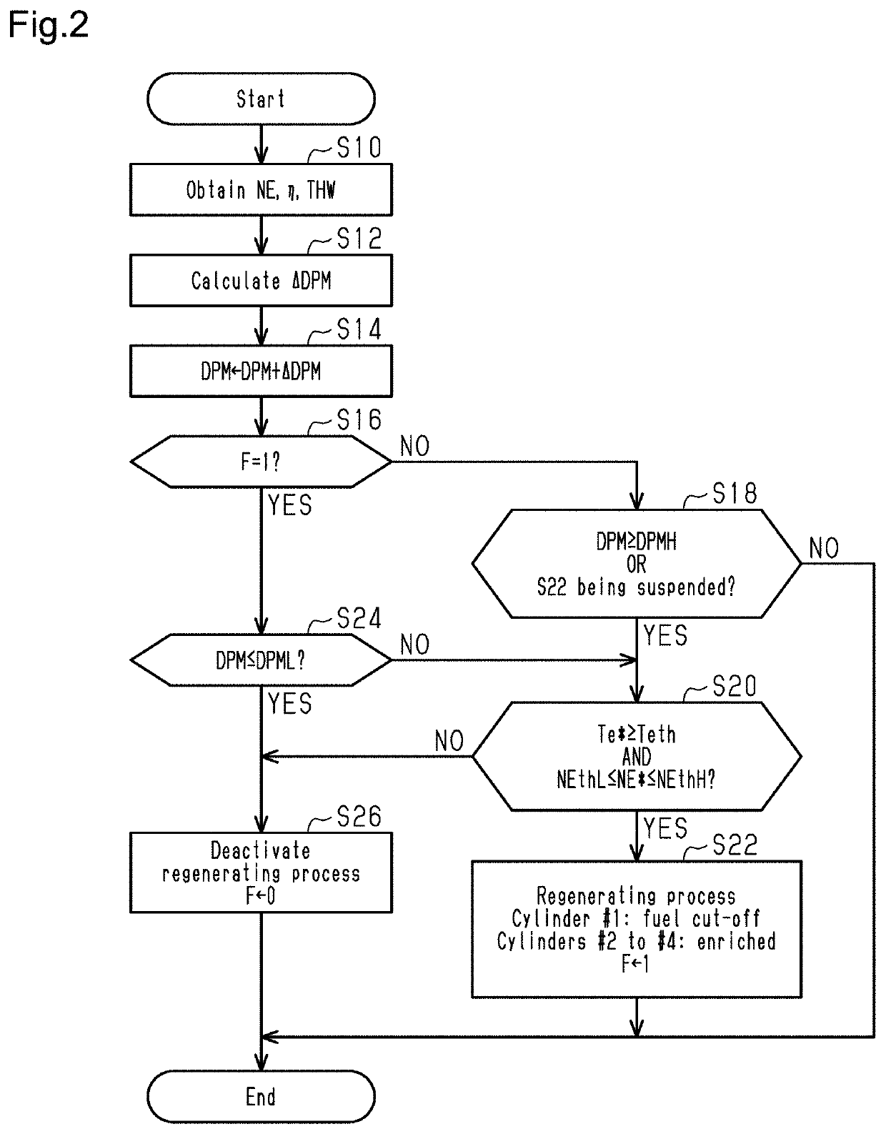
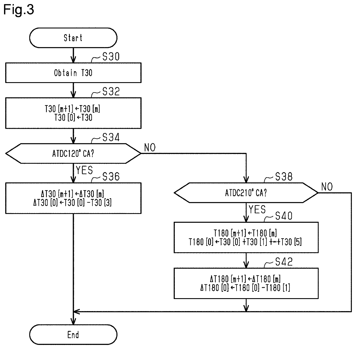
[0031]An embodiment will now be described with reference to FIGS. 1 to 7.

[0032]As shown in FIG. 1, an internal combustion engine 10 includes four cylinders #1 to #4. In the internal combustion engine 10, the c...


PUM


Abstract

A misfire detection device and method for an internal combustion engine are provided. A deactivating process deactivates combustion control for air-fuel mixture in a deactivated cylinder. An instantaneous speed variable indicates a speed in a case where a crankshaft rotates by a specific angle. The specific angle of the first instantaneous speed variable is a first angle. The specific angle of the second instantaneous speed variable is a second angle greater than the first angle. A second determining process determines whether a misfire has occurred from a magnitude of a rotation fluctuation amount of a subject of determination, instead of a relative magnitude of the rotation fluctuation amount of the subject of the determination relative to a reference rotation fluctuation amount, when the reference rotation fluctuation amount is a rotation fluctuation amount of the deactivated cylinder during the execution of the deactivating process.

Description

BACKGROUND1. Field[0001]The present disclosure relates to a misfire detection device for an internal combustion engine, a misfire detection method for an internal combustion engine, and a memory medium.2. Description of Related Art[0002]Japanese Laid-Open Patent Publication No. 2009-138663 discloses an example of a misfire detection device that uses a rotation fluctuation amount to determine whether a misfire has occurred. The rotation fluctuation amount is the fluctuation amount of an instantaneous rotation speed. The instantaneous rotation speed is the rotation speed of a crankshaft in an interval that is shorter than the occurrence interval of a compression top dead center. More specifically, whether a misfire has occurred is determined from the difference between a threshold value and the difference between rotation fluctuation amounts that are separated from each other by 360° crank angle (CA). That is, the threshold value is not directly compared with a rotation fluctuation am...

Claims


Application Information

Patent Timeline
Patent Type & Authority Applications(United States)
IPC IPC(8): F02D41/14
CPCF02D41/1498F02D2200/101F02D2200/1015F02D45/00F02D41/3094F02D41/1448F02D41/0087
Inventor SUGIMOTO, HITOKI
Owner TOYOTA JIDOSHA KK
Learn More