
Fluctuation attenuator

a technology of attenuator and rotor, which is applied in the direction of spring/damper, vibration suppression adjustment, mechanical equipment, etc., to achieve the effect of preventing the reduction of the cushioning function, suppressing the relatively large fluctuation of the angular acceleration of the motor, and transmitting the torque fluctuation between the first rotor

Active Publication Date: 2019-01-15
HONDA MOTOR CO LTD
View PDF6 Cites 0 Cited by
  • Summary
  • Abstract
  • Description
  • Claims
  • Application Information

AI Technical Summary

Benefits of technology

The present invention aims to provide a fluctuation attenuator that can suppress the fluctuation of angular acceleration when a rotor collides with a supporting member. The invention utilizes an elastic body which has an exposed end portion. This exposed end portion can follow the second rotor when the supporting member becomes separated from the rotor during high-speed rotation. This prevents a reduction in the cushioning function of the elastic body and the suppression of impact when the rotor comes into contact with the supporting member. Additionally, a clearance portion is provided on the supporting member to prevent the elastic body from sticking to the supporting member. This ensures the proper functioning of the elastic body and prevents any increase in the fluctuation of angular acceleration of the motor.

Problems solved by technology

When the stuck supporting member collides with the second rotor, a motor detects the large fluctuation of angular acceleration, and may misdetect as an accidental fire including an ignition failure of the motor.

Method used


Image

  • Fluctuation attenuator
  • Fluctuation attenuator
  • Fluctuation attenuator

Examples


Embodiment Construction

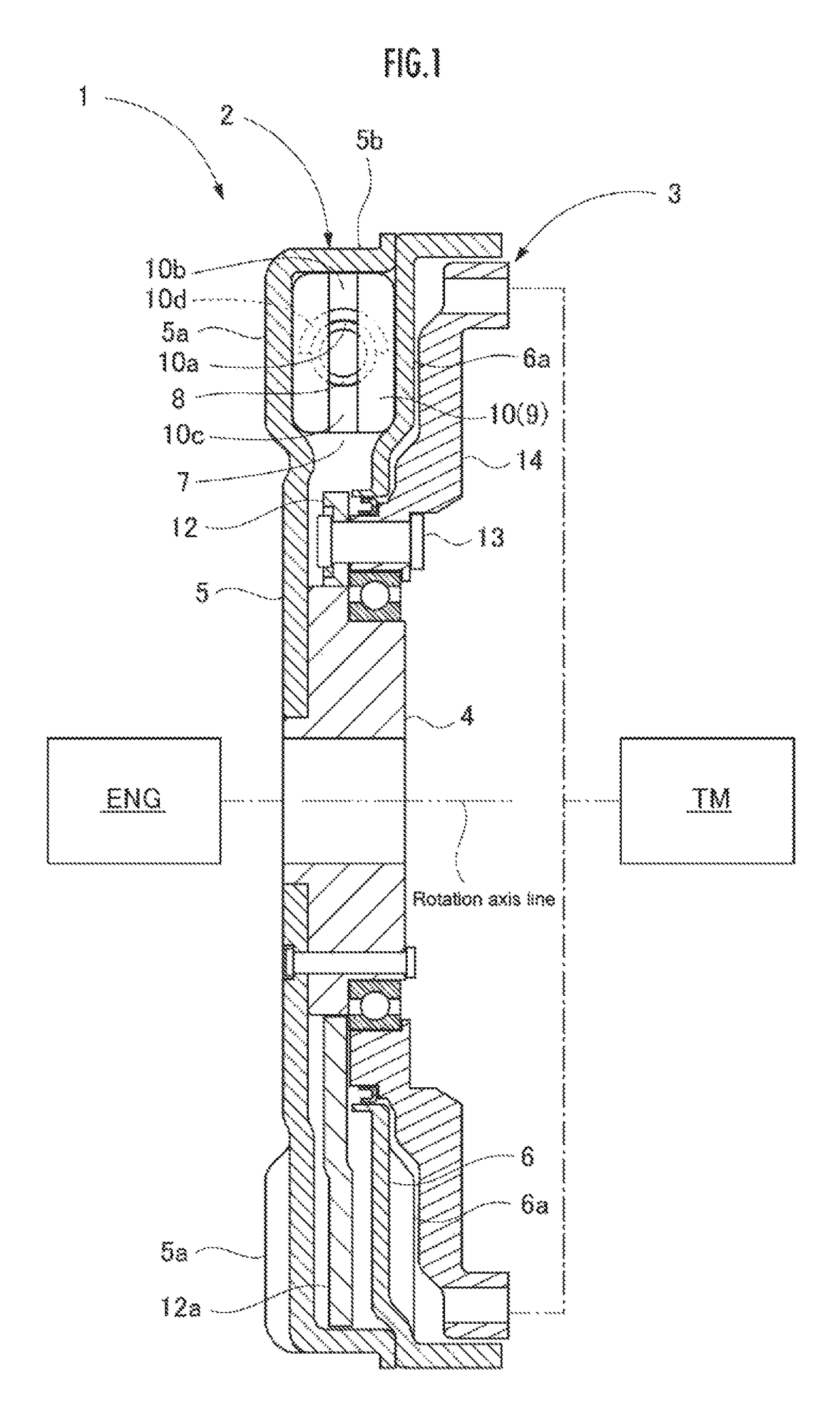
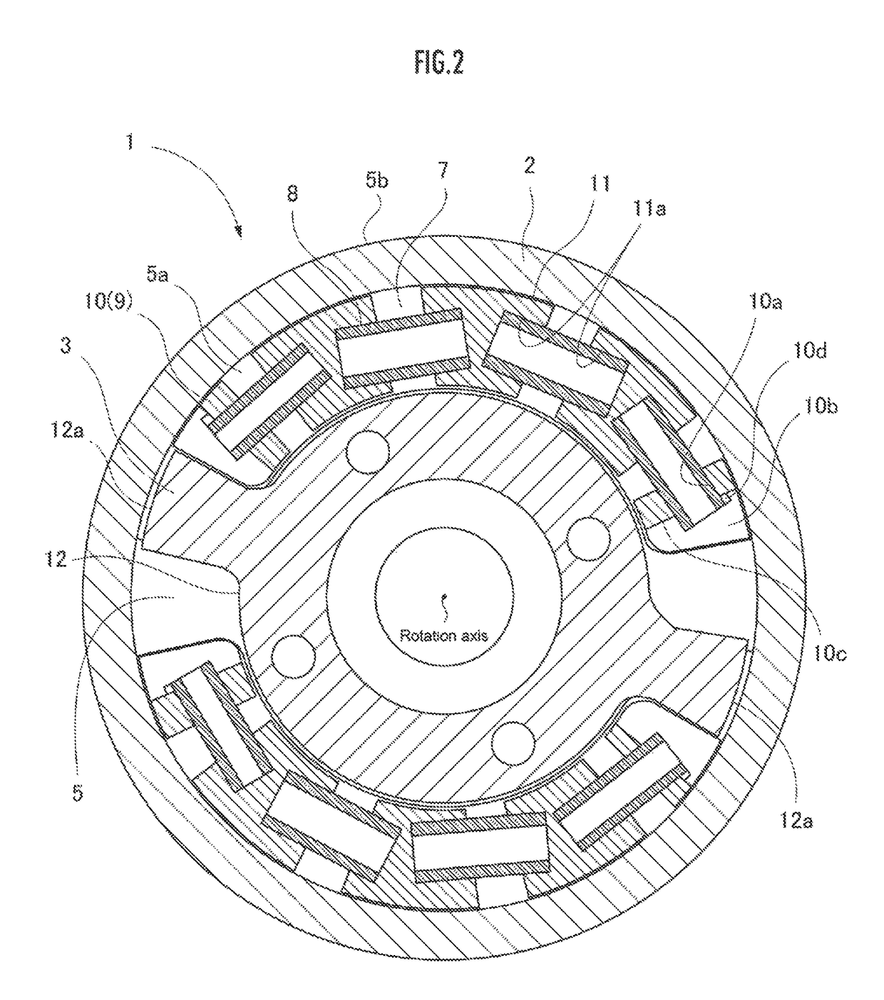
[0027]A fluctuation attenuator in the embodiment of the present invention is a dual mass flywheel 1 which is a kind of variable capacity flywheel. As shown in FIG. 1 and FIG. 2, the dual mass flywheel 1 has a first flywheel 2 as a first rotor connected to a crank shaft of an internal combustion engine ENG as a motor, a second flywheel 3 as a second rotor connected to an input shaft of a transmission TM as a power transmission device, and the first flywheel 2 as the second rotor which enables the relative angular displacement with the first flywheel 2 around the same axis line relative to the first flywheel.

[0028]The first flywheel 2 has an shaft body 4 connected to the crank shaft of the internal combustion engine ENG, a disc-shaped first plate 5 fixed on the shaft body 4, and a disc-shaped second plate 6 disposed on the same axis with the first plate 5 so as to be further separated from an internal combustion engine ENG than the first plate 5.

[0029]A pair of first recessed portions...


PUM


Abstract

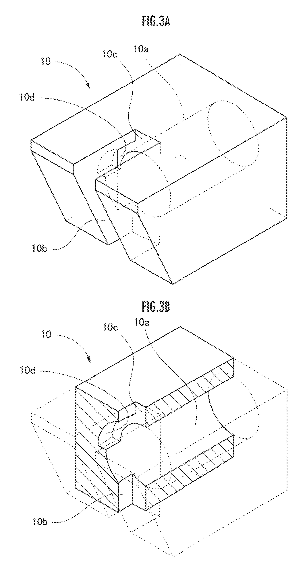
A fluctuation attenuator has: a first flywheel 2 connected to an internal combustion engine ENG; a housing portion 7; a second flywheel 3 connected a transmission TM; a plurality of end portion sheets 10 inserted into the housing portion 7; and a coil spring 8 held on the end portion sheet 10. The end portion sheet 10 has an inserting hole 10a into which the coil spring 8 inserted, and a notched portion 10b into which a projecting piece 12a of the second flywheel 3 is inserted and with which the inserting hole 10a is communicated, and which exposes the end portion of the coil spring 8. A notched portion 10b is notched such that the projecting piece 12a contacts the end portion sheet 10 after contacting the coil spring 8 when the projecting piece 12a contacts the end portion sheet 10.

Description

CROSS-REFERENCE OF RELATED APPLICATION[0001]This application claims priority of Japanese Patent Application No. 2015-216658 filed in Japan on Nov. 4, 2015, the entire contents of which are incorporated herein by reference.TECHNICAL FIELD[0002]The present invention relates to a fluctuation attenuator attenuating the fluctuation of the driving force which is transmitted between a motor and a power transmission device.BACKGROUND OF THE INVENTION[0003]There is an conventionally known fluctuation attenuator which transmits the driving force output from the internal combustion engine to a transmission, and simultaneously, attenuates the fluctuation of the driving force of the internal combustion engine (for example, see Japanese Laid-open Patent Publication No. 2015-86965).[0004]The fluctuation attenuator has a first flywheel connected to an internal combustion engine, a housing portion provided on the first flywheel, a second flywheel connected to the transmission so as to enable the rel...

Claims


Application Information

Patent Timeline
Patent Type & Authority Patents(United States)
IPC IPC(8): F16F15/121F16F15/123
CPCF16F15/12326F16F15/1232
Inventor MURATA, TOSHIKISATO, YOSHINORI
Owner HONDA MOTOR CO LTD
Learn More