Engine control system

a control system and engine technology, applied in the direction of electrical control, process and machine control, instruments, etc., can solve the problems of deterioration of exhaust emission characteristics due to remaining fuel, and achieve high accuracy and high robustness

Inactive Publication Date: 2010-11-23
HITACHI LTD
View PDF11 Cites 3 Cited by
  • Summary
  • Abstract
  • Description
  • Claims
  • Application Information

AI Technical Summary

Benefits of technology

[0007]The present invention considers the above circumstance, and its object is to propose an engine control system capable of controlling the combustion air-fuel ratio from just after the engine starting with high accuracy and high robustness.
[0010]According to the practical mode, since the residual fuel quantity is not predicted but can be obtained by calculating the fuel quantity flowing (burning) actually into the combustion chamber, there are no problem of the temperature estimation accuracy on the inlet valve and it is also able to correspond to fuel property changes. Therefore, it is capable of suppressing the influence on the residual fuel flowing on the wall in the intake passage and / or cylinder at engine starting with high accuracy and high robustness.
[0026]Namely, according to the practical mode, it is capable of computing the combustion fuel quantity by sensing directly or indirectly the combustion pressure (a mean effective pressure) in the combustion chamber. Also, by sensing directly or indirectly the air-fuel ratio in the combustion chamber, it is capable of computing the combustion fuel quantity on the basis of air quantity in the combustion chamber (filling efficiency). In addition, by sensing directly or indirectly the in-cylinder gas temperature, it is capable of estimating the in-cylinder pressure or air-fuel ratio, as a result, estimating the combustion fuel quantity becomes possible.

Problems solved by technology

Then, as time goes by, since the adhering fuel becomes fuel flow on a wall surface of the intake passage and gradually flows into the combustion chamber and results in degradation of the air-fuel ratio, the deterioration of the exhaust emission characteristic is caused.
After that, as time goes by, since the remaining fuel burns at next and subsequent times in the combustion chamber, deterioration of the exhaust emission characteristic is caused due to the remaining fuel.
Additionally, when the operation condition of the engine changes, for example, a filling efficiency changes, deterioration of the exhaust emission characteristic is caused as in the case of the above-mentioned adhered fuel flowing on a wall surface at the engine starting.
Namely, there is a problem of a low robustness.
However, keeping the estimation accuracy is a quite difficult from the viewpoint of information of the current sensor (engine cooling water temperature sensor and intake air temperature), because heat conductivity characteristic to the inlet valve is complicated.
Therefore, complicated computation needs to estimate these quantities and an error cause may be increase.
Further, as the suction coefficient is determined based on a certain fuel property, if the suction fuel quantity is estimated using the suction coefficient when the fuel property changes, an error occurs.
As described above, estimation computation is difficult in corresponding various kinds of the condition changes and its low robust is a problem.

Method used


Image

  • Engine control system
  • Engine control system
  • Engine control system

Examples


first embodiment

FIGS. 20 to 24

[0105]FIG. 20 shows the control system 1A of the first embodiment (the second and third embodiments also are the same as the first embodiment). The control unit 100 of the control system 1A as shown in a function block diagram, comprises a basic injection fuel quantity computing means 120, an injection fuel quantity-correction coefficient computing means 130, a combustion fuel quantity computing means 140 as a combustion fuel quantity determining, and a residual fuel quantity computing means 150. The injection fuel quantity-correction coefficient computing means 130 computes a correction coefficient value Tp_hos1 for each cylinder. The control unit 100 multiplies the basic injection fuel quantity Tp by Tp_hos1 (correction coefficient value), thereby the injection fuel quantity (Ti) for each cylinder is obtained so as to maintain the each cylinder combustion air-fuel ratio at a desired air-fuel ratio. In particular, the value (Tp_hos1) computed by the injection fuel qua...

second embodiment

The Second Embodiment

FIGS. 25 and 26

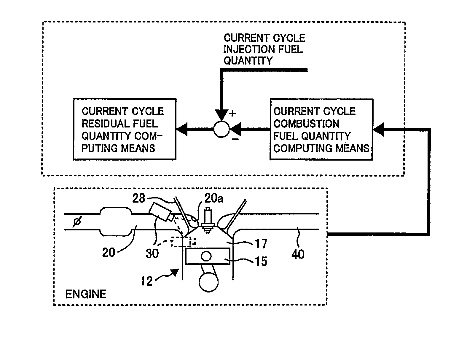
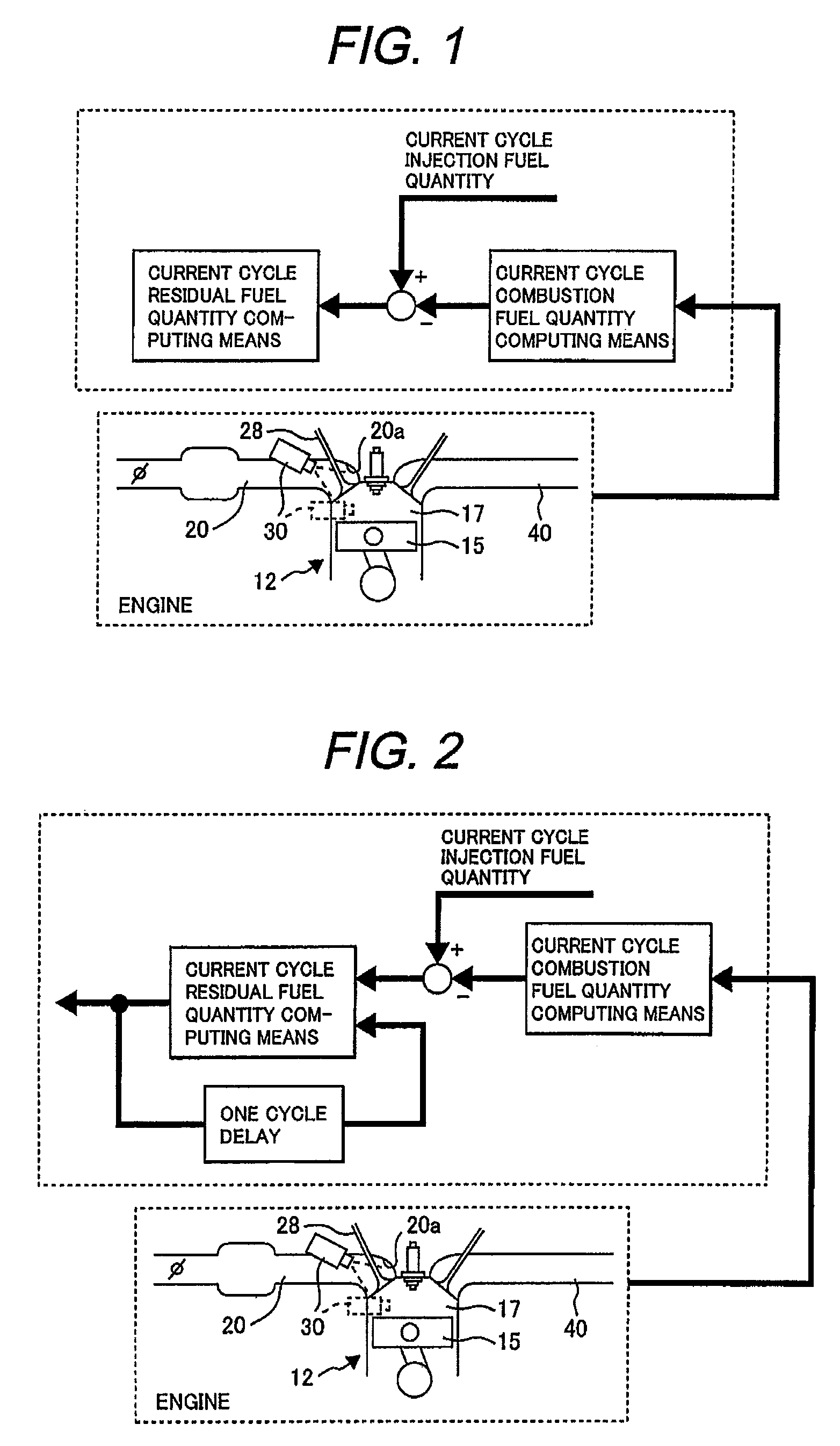
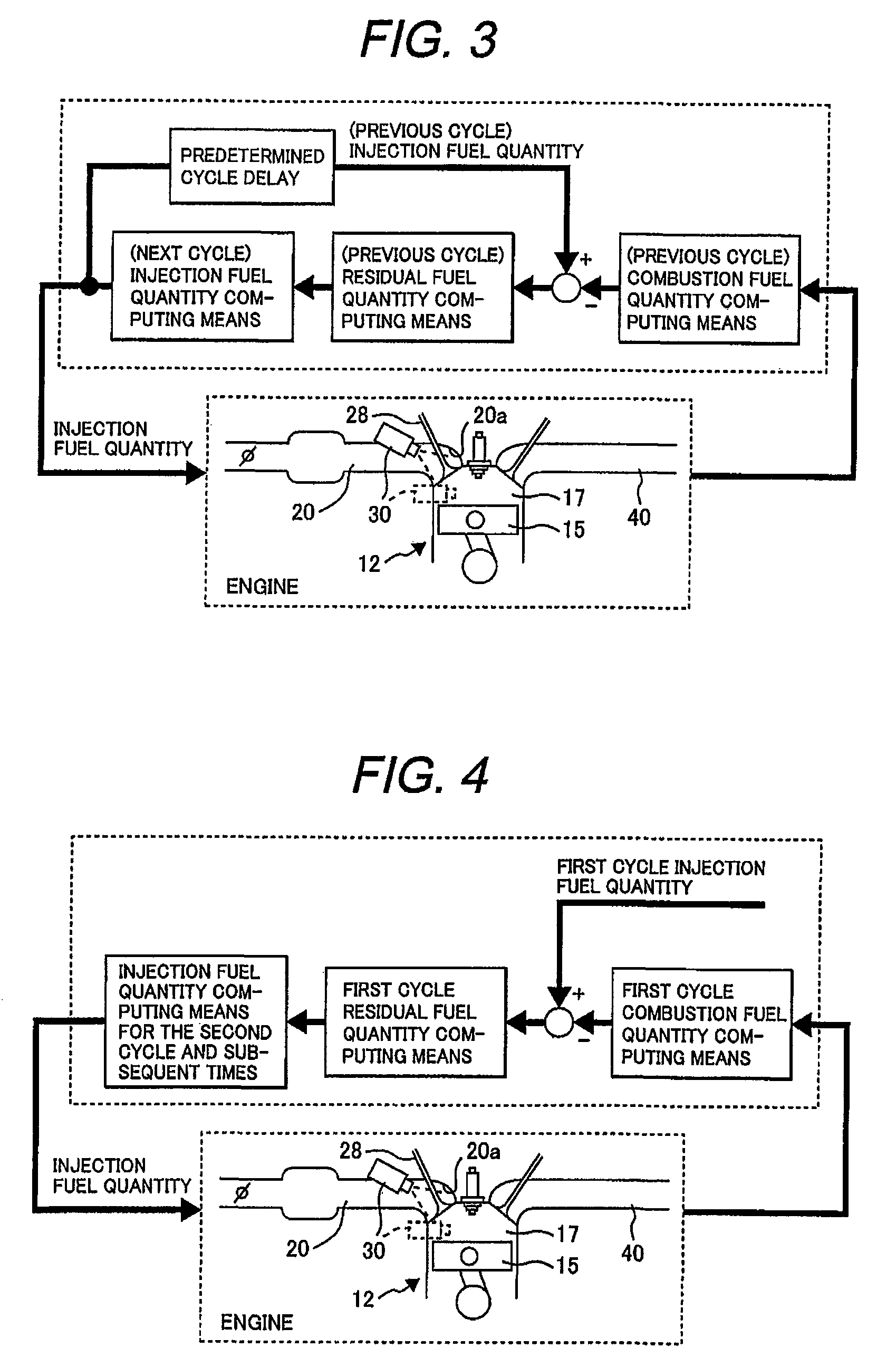
[0113]In the first embodiment shown as above, the residual fuel quantity (Fuel_R) only in the first cycle is obtained, however, in the second embodiment, the residual fuel quantity in the second and subsequent times is obtained.

[0114]The second embodiment differs from the first embodiment in only structures and functions of the combustion fuel computing means (which is denoted by reference numeral 140 in the first embodiment and by reference numeral 240 in the second embodiment) and the residual fuel quantity computing means (which is denoted by reference numeral 150 in the first embodiment and by reference numeral 250 in the second embodiment), and both are the same except for that. Therefore, hereinafter, mainly explained are the combustion fuel quantity computing means 240 and the residual fuel quantity computing means 250.

240 (FIG. 25)>

[0115]The computing means 240 obtains the combustion fuel quantity (Fuel_C) based on the engine speed (Ne). T...

third embodiment

FIGS. 27 and 28

[0119]In the second embodiment as shown above, the residual fuel quantity for the next cycle and subsequent times is computed by using the combustion fuel quantity (angular acceleration). In contrast to this, in the third embodiment, the residual fuel quantity in the first cycle is obtained by using the combustion fuel quantity, and the residual fuel quantity for the second cycle and subsequent times is obtained by the surface temperature of the inlet valve 28.

[0120]The third embodiment differs from the first and second embodiments in only structure and function of the residual fuel quantity computing means (which is denoted by reference numeral 150 in the first embodiment, by reference numeral 250 in the second embodiment and by reference numeral 350 in the third embodiment), and they are the same except for that. Therefore, hereinafter, mainly explained is the residual fuel quantity computing means 350 and an inlet valve-surface temperature estimating means 355 incl...


PUM


Abstract

An engine control system for an internal combustion engine with a fuel injector, comprises a combustion fuel quantity computing means for computing a combustion fuel quantity in a combustion cycle; and a residual fuel quantity computing means for computing a residual fuel quantity in the combustion cycle based on a difference between an injection fuel quantity of the fuel injector and the combustion fuel quantity.

Description

CLAIM OF PRIORITY[0001]The present application claims priority from Japanese application serial No. 2006-247113, filed on Sep. 12, 2006, the contents of which are hereby incorporated by references into this application.FIELD OF THE INVENTION[0002]The present invention relates to an engine control system for computing an injection fuel quantity every cycle, particularly, to an engine control system robust and effective in improving air-fuel control accuracy at engine starting.BACKGROUND ART[0003]Recently, it is required strongly to improve engine exhaust gas emission characteristics in USA, Europe, Japan and the like with tightening of emission control of automobile internal combustion engines. As high performance of a catalyst and high accuracy of a catalyst control are improved, the emission characteristic of the engine exhaust gas discharged at engine starting has become most important. Improvement of air-fuel ratio control accuracy is effective to improve the emission characteris...

Claims


Application Information

Patent Timeline
Patent Type & Authority Patents(United States)
IPC IPC(8): B60T7/12G05D1/00
CPCF02D41/047F02D41/06F02D41/34F02D35/023F02D41/008F02D41/1497F02D2200/0614Y02T10/44F02D35/025F02M25/07F02D21/00F02M26/00Y02T10/40
Inventor NAKAGAWA, SHINJIKANETOSHI, KAZUHIKOKATOGI, KOZOICHIHARA, TAKANOBUOSUGA, MINORU
Owner HITACHI LTD
Why Eureka
Try Eureka