Hydraulic prosthetic joint

a prosthetic joint and hydraulic technology, applied in the field of artificial limbs, can solve the problems of unwelcome stares of amputees, knees becoming automatically locked, and resistance often so grea

Active Publication Date: 2014-12-23
BOENDER JACOB QUINTUS LAURENS ANTHONY
View PDF16 Cites 10 Cited by
  • Summary
  • Abstract
  • Description
  • Claims
  • Application Information

AI Technical Summary

Benefits of technology

[0016]It is a still further object of the invention to provide a simple to use prosthesis which is not vulnerable to ingress of water and dirt and can be both simply and easily cleaned. Another object of the invention to provide a leg prosthesis that enables a more immediate release of a memory function, but remain sensitive to a required completion of the knee flexion movement in the first half of the swing phase, when required as is the case across uneven terrain.STATEMENT OF INVENTION
[0023]Thus, in one aspect of the present invention, upon a return to a natural weight accepting state of the knee joint there is no delay to a further state of movement of the joint, for example, upon the occurrence of lifting off the weight of a body upon a prosthesis, the lower part is free to swing in a controlled fashion i.e. a state permitting free knee flexion), this by drawing on the energizing and informing potential of the existing reverse pressure differentials present during the extension phase in the second half of the swing phase. Due to the relative high levels of energizing power available during knee extension and the distinct and logical onset of its availability, its use is an inherent advance in the logical control of an artificial hydraulic knee. Notwithstanding this, if further delay is required, then additional control systems could be employed, to act in an ancillary fashion. A further enhancement and alternative is the making available to a user an adjustable time delay for the memory to turn to a default sate.

Problems solved by technology

It can be said that the test is somewhat subjective if one were to view an amputee with an artificial leg, but mere observation is one of the best tests; a strange gait is generally immediately apparent; this can cause unwelcome stares to amputees, who when fitted with a pair of long trousers would otherwise not be noticed when in a crowd.
In this device, however, an axial load on the limb produced a small rotation of the radius arm or arms causing the brake band or brake shoe to grip the drum and to resist knee flexion.
Indeed, the resistance would frequently become so great such that the knee became automatically locked once sufficient load had been applied.
In some situations, however, this system required an amputee to make a knee-extending movement before flexion could be initiated.
Additional problems arose through external wear and through the fact that they require actuation, which is, of course dependent upon movement being regular.
In some cases mechanical switching of the valve will not be effected properly.
Whilst recent hydraulic devices are believed to be much improved they are complex and costly to manufacture; they are manufactured to high tolerances.
If mechanical external valve control is provided, then there will be problems as discussed above.
In simple terms, to the casual observer, the person wearing such artificial limbs would be seen to have an ungainly gait due to a delay in knee extension needed to prepare the limb for weight acceptance.
A horizontal response was produced but the study was limited to below 5 km / hr limit, which is less than normal walking speeds.
Problems arising from the use of weight activated knee joint control mechanisms include the fact that the residual weight taken by the artificial limb on toe off can be inhibitive to the release of the weight-activated mechanism.
This threshold is easily overcome by force entry through the heel and is not easily overcome by force entry through the toe.
Nevertheless, this threshold takes away from the ease of activation on heel strike, which subtracts from the total ease of use of the artificial limb, and low grades of attention will be needed at all times.
The same threshold also makes it difficult to find instant effortless stability of the knee, when extension after mid swing is incomplete the respective foot is susceptible of hitting the ground too early.
Typically the weight-activation class of knee joints do not provide security against collapse in such conditions or in the event of accidental use.
One difficulty to be overcome by users of prosthetic lower limbs is that it is counter intuitive to place one's body weight onto the device to secure the same body weight against sudden collapse.
In the event of an inadvertent early reapplication of weight on the prosthesis, the toggle would likely not be in a position to allow closure of the valve, which could be painful and perhaps cause an amputee to fall over following knee collapse in such circumstances.

Method used


Image

  • Hydraulic prosthetic joint
  • Hydraulic prosthetic joint
  • Hydraulic prosthetic joint

Examples


Embodiment Construction

[0043]There will now be described, by way of example only, the best mode contemplated by the inventor for carrying out the present invention. In the following description, numerous specific details are set out in order to provide a complete understanding to the present invention. It will be apparent to those skilled in the art, that the present invention may be put into practice with variations of the specific.

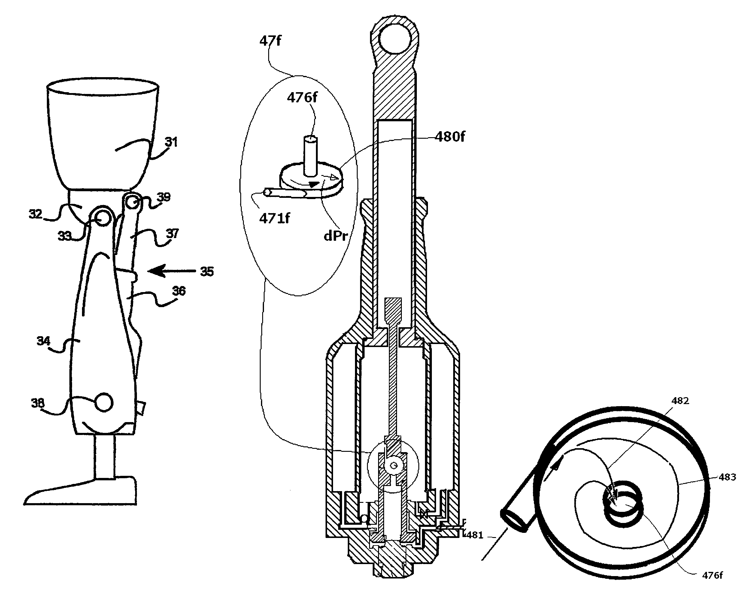
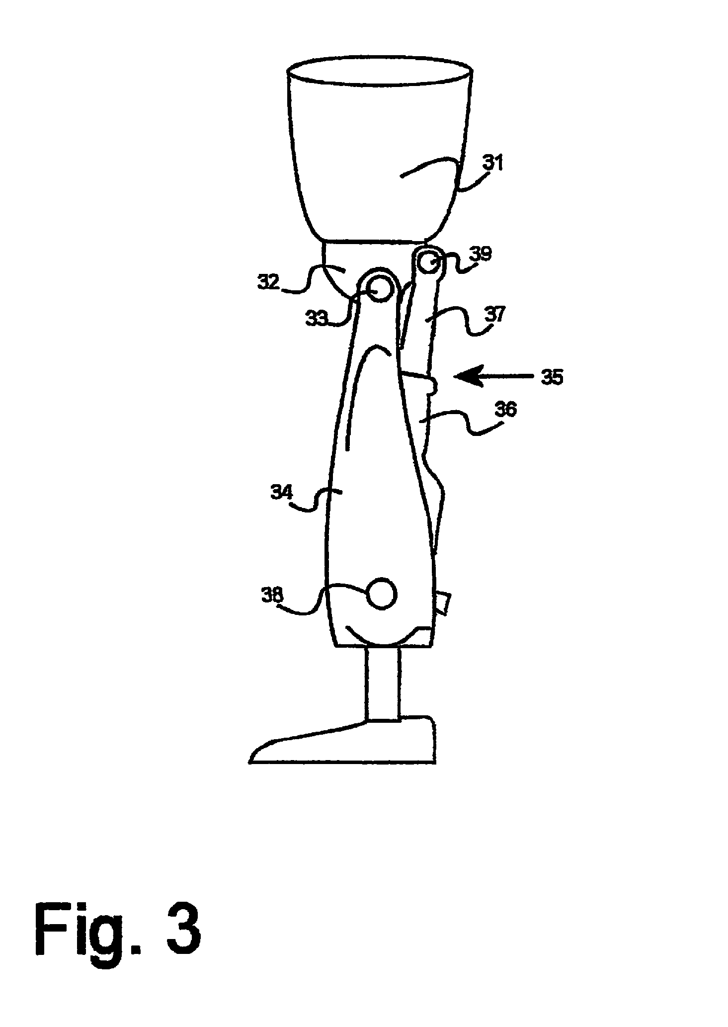
[0044]FIG. 3 shows a simple artificial leg arrangement 30, wherein an upper leg member 31 terminates with a stump element 32, which is pivotally connected to a lower leg member 34 by means of joint 33. A main body 36 of a hydraulic damper 35, having a main body 36, is connected with the lower leg 34 at coupling point 38, which coupling point 38 allows relative movement therebetween. A member 37 of the hydraulic damper 35 is connected to the stump element 32 at coupling point 39 and is similarly arranged for movement, in this case, relative to the stump element 32. Whilst the f...


PUM


Abstract

The present invention relates to artificial limbs generally and to joints for the same. In particular, the present invention provides hydraulic functional units (35), generally classified as damping devices as connected between artificial limbs whereby to enable movement of artificial joints to closely correspond with natural human movement. In the provision of realistic joints, as used in prosthetic limbs, an important aspect in attempting to achieve a realistic movement is to provide a different operating characteristic to the joint when under load. Indeed, one of the more important characteristics of an artificial leg for achieving a natural-looking walking gait correspond with those of a so called stabilized knee, i.e. a knee which resists flexion when under load, that is when it is bearing at least some of the weight of the amputee. In accordance with the invention, there is provided hydraulic damper control elements for prostheses which utilize a pressure differential due to the presence a fluid flow as a direct control input for a at least one hydraulic valve (47). The valve can comprise a vortex flow arrangement (47f) to cause fluid flow to circulate about aperture. The valve can comprise a moveable element which abuts a resiliently mounted element which reduces the size of an aperture as the force increases.

Description

FIELD OF THE INVENTION[0001]The present invention relates to artificial limbs generally and to joints for the same. In particular, the present invention provides hydraulic functional units, generally classified as damping devices as connected between artificial limbs whereby to enable movement of artificial joints to closely correspond with natural human movement.BACKGROUND[0002]In the provision of realistic joints, as used in prosthetic limbs, an important aspect in attempting to achieve a realistic movement is to provide a different operating characteristic to the joint when under load. Indeed, one of the more important characteristics of an artificial leg for achieving a natural-looking walking gait correspond with those of a so called stabilised knee, i.e. a knee which resists flexion when under load, that is when it is bearing at least some of the weight of the amputee. It can be said that the test is somewhat subjective if one were to view an amputee with an artificial leg, bu...

Claims


Application Information

Patent Timeline
Patent Type & Authority Patents(United States)
IPC IPC(8): A61F2/68A61F2/74F16F9/512A61F2/60A61F2/64A61F2/50A61F2/76
CPCA61F2/642A61F2002/741A61F2/605A61F2002/5018A61F2002/7635A61F2/68A61F2002/5006A61F2002/745F16F9/512A61F2002/5007A61F2002/5033A61F2002/748A61F2002/5039A61F2/74A61F2/741A61F2/748A61F2/58A61F2/64F16F9/34
Inventor BOENDER, JACOB, QUINTUS, LAURENS, ANTHONY
Owner BOENDER JACOB QUINTUS LAURENS ANTHONY
Why Eureka
Try Eureka