
Wireless communication apparatus and antenna device

a communication device and antenna technology, applied in the field of wireless communication devices, can solve the problems of large spurious radiation generated by the rfid device, large radiation, and driven wireless ic of the rfid system, and achieve the effect of significantly reducing or preventing the adverse effects of the first communication system on the transmission signal of the second communication system

Active Publication Date: 2014-12-23
MURATA MFG CO LTD
View PDF12 Cites 0 Cited by
  • Summary
  • Abstract
  • Description
  • Claims
  • Application Information

AI Technical Summary

Benefits of technology

The patent is about a wireless communication device that can minimize the impact of one communication system on the signals of another communication system. The device can prevent the first system from affecting the second system's signals.

Problems solved by technology

In this case, when a transmission wave of the cellular system is input to the RFID device, there is a concern that the wireless IC of the RFID system is driven and spurious radiation occurs.
Furthermore, since the transmission power is large, spurious radiation generated by the RFID device is large.
That is, there is a problem that part of transmission signals of the cellular system, such as the GSM, flows into the RFID device so that the characteristic (communication sensitivity) of the transmission signals deteriorates.
Harmonics in the 900 MHz band are used in other systems, such as GSM 1800 and W-LAN, in many cases, and there is another problem that spurious radiation from the RFID device becomes noise and causes adverse effects on those systems.

Method used


Image

  • Wireless communication apparatus and antenna device
  • Wireless communication apparatus and antenna device
  • Wireless communication apparatus and antenna device

Examples


Embodiment Construction

[0031]Hereinafter, examples of a wireless communication apparatus and an antenna device according to various preferred embodiments of the present invention will be described with reference to the attached drawings. Common elements and parts are referred to using the same reference marks throughout the drawings, and the repetitive description is omitted.

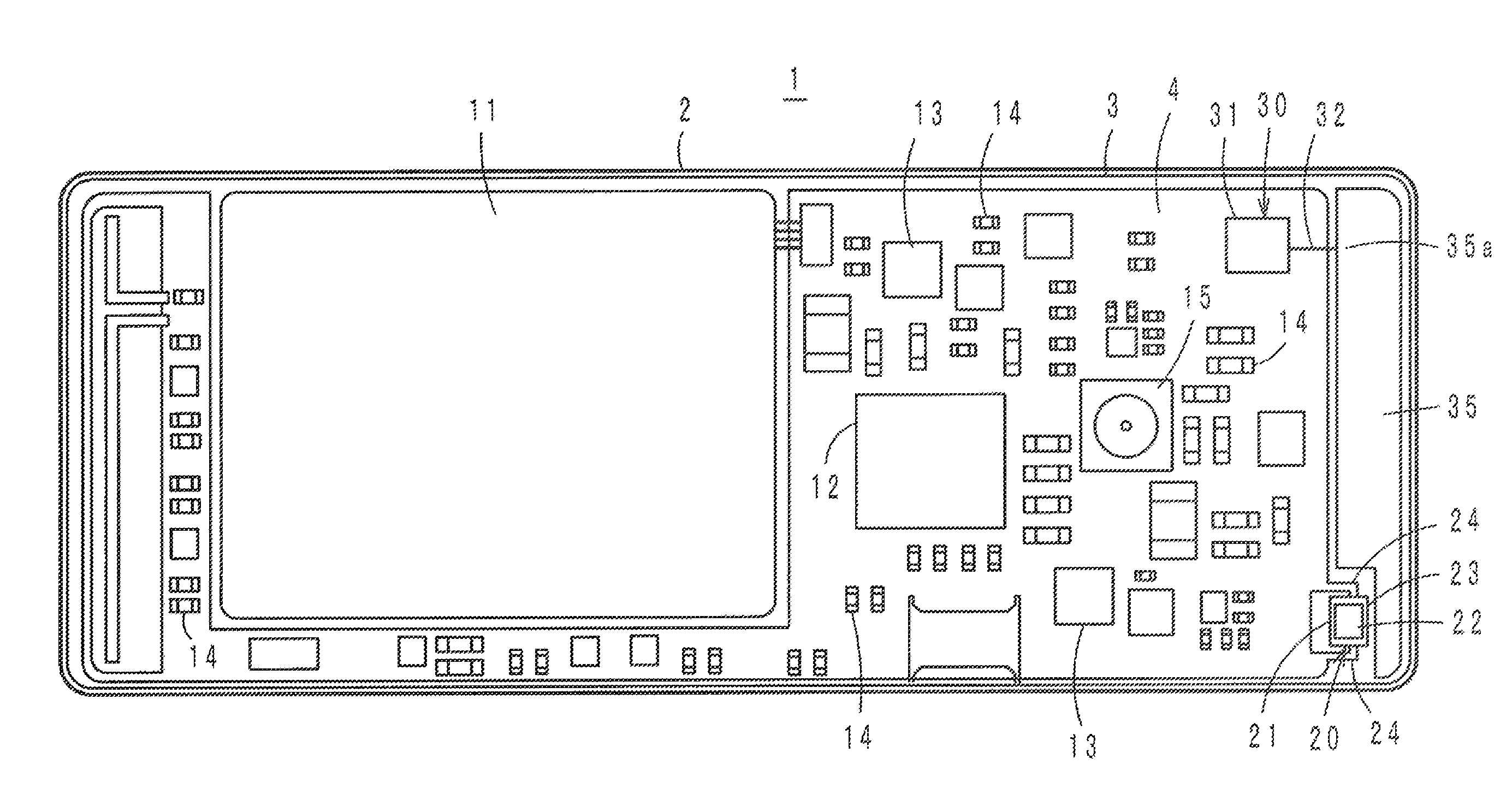
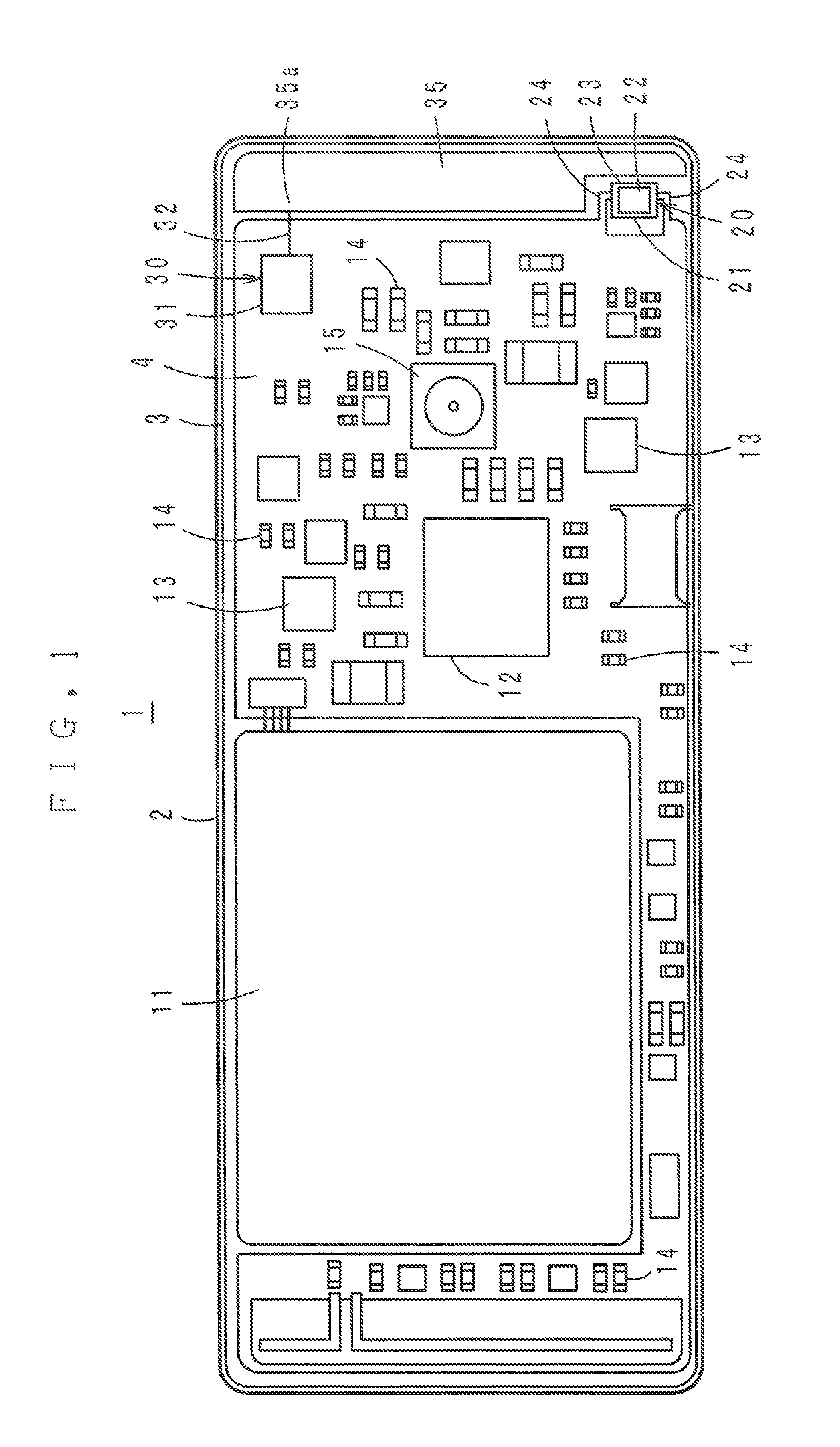
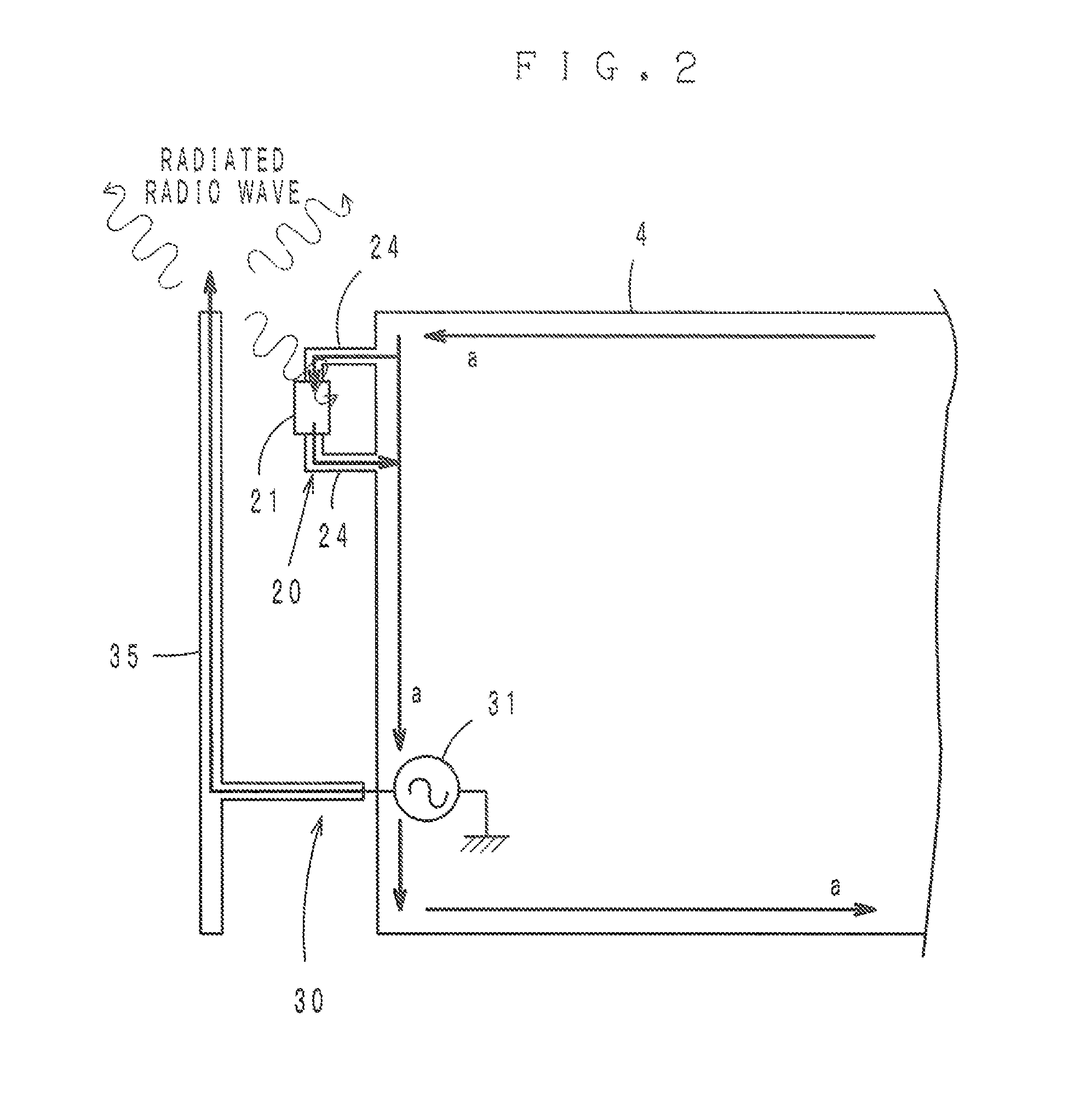
[0032]A wireless communication apparatus 1 shown in FIG. 1 preferably is a cell phone, including a cellular (GSM) system 30 which is an example of the second communication system, and further including an RFID system 20 which is an example of the first communication system. On a printed wiring board 3 incorporated in a case 2, a battery 11, a switching module 12, various ICs 13, elements 14 such as chip resistors and chip capacitors, a digital camera 15, etc., are mounted.

[0033]The cellular system 30 includes a main antenna 35 provided at one end of the printed wiring board 3 and a wireless IC 31. The main antenna 35 includes a power ...


PUM


Abstract

A wireless communication apparatus includes a first communication system, and a second communication system configured to transmit a transmission signal in a communication frequency band which is the same or substantially the same as that of the first communication system and at an electric power which is stronger than that of a reception signal of the first communication system. The first communication system includes a feeder circuit having a resonant frequency, the resonant frequency being within the communication frequency band if a reception signal of the first communication system is input, and the resonant frequency being out of the communication frequency band if a transmission signal of the second communication system is input.

Description

[0001]This application is based on Japanese Patent Application No. 2012-252570 filed on Nov. 16, 2012 and International Application No. PCT / JP2013 / 080453 filed on Nov. 11, 2013, the entire contents of each of which is incorporated herein by reference.BACKGROUND OF THE INVENTION[0002]1. Field of the Invention[0003]The present invention relates to wireless communication apparatuses and more specifically to a wireless communication apparatus including a communication system preferably for use in an RFID (Radio Frequency Identification) system and a communication system such as a cell phone, and relates to an antenna device which is used for an RFID system in the wireless communication apparatus.[0004]2. Description of the Related Art[0005]In recent years, as an information management system for articles, the RFID system has been in practical use which establishes communication between a reader / writer for generating an induced magnetic field and an RFID tag (also referred to as “RFID de...

Claims


Application Information

Patent Timeline
Patent Type & Authority Patents(United States)
IPC IPC(8): H04Q5/22G06K7/00H04B5/48
CPCH01Q1/243H01Q9/42H04B1/18G06K7/0008H04B1/005H01Q3/44H04B1/38H04B5/48H01Q1/38
Inventor TAKEOKA, MAKOTOKATO, NOBORUYASUTAKE, MAKOTO
Owner MURATA MFG CO LTD
Learn More