Sliding vane geometry turbines

a turbine and sliding vane technology, applied in the direction of machines/engines, stators, liquid fuel engines, etc., can solve the problems of energy loss, decreased cross-section of the nozzle channel, etc., and achieve the effect of reducing expansion losses

Active Publication Date: 2014-12-30
FORD GLOBAL TECH LLC
View PDF27 Cites 7 Cited by
  • Summary
  • Abstract
  • Description
  • Claims
  • Application Information

AI Technical Summary

Benefits of technology

[0007]The inventors herein have recognized the above issues and have devised an approach to at least partially address them. In one example, an annular turbine nozzle comprises a central axis and a nozzle vane. The nozzle vane includes a stationary vane and a sliding vane. The stationary vane includes a sliding surface in contact with a sliding surface of the sliding vane. The sliding vane is positioned to slide in a direction substantially tangent to an inner circumference of the turbine nozzle. Thus, a desired angle of incidence may be substantially maintained over a range of engine operating conditions. Further, expansion losses may be reduced as compared to a turbine nozzle with an annular sliding ring.

Problems solved by technology

Thus, the swing nozzle vane creates a trade-off between turbine efficiency at high exhaust gas flows or at low exhaust gas flows because the cross-sectional area of the channels and the angle of incidence cannot be varied independently.
At small exhaust flows, the turbine nozzle channels have a decreased cross-section and energy is lost when the exhaust gas expands from the small turbine nozzle channel to the larger turbine inlet.

Method used


Image

  • Sliding vane geometry turbines
  • Sliding vane geometry turbines
  • Sliding vane geometry turbines

Examples


Embodiment Construction

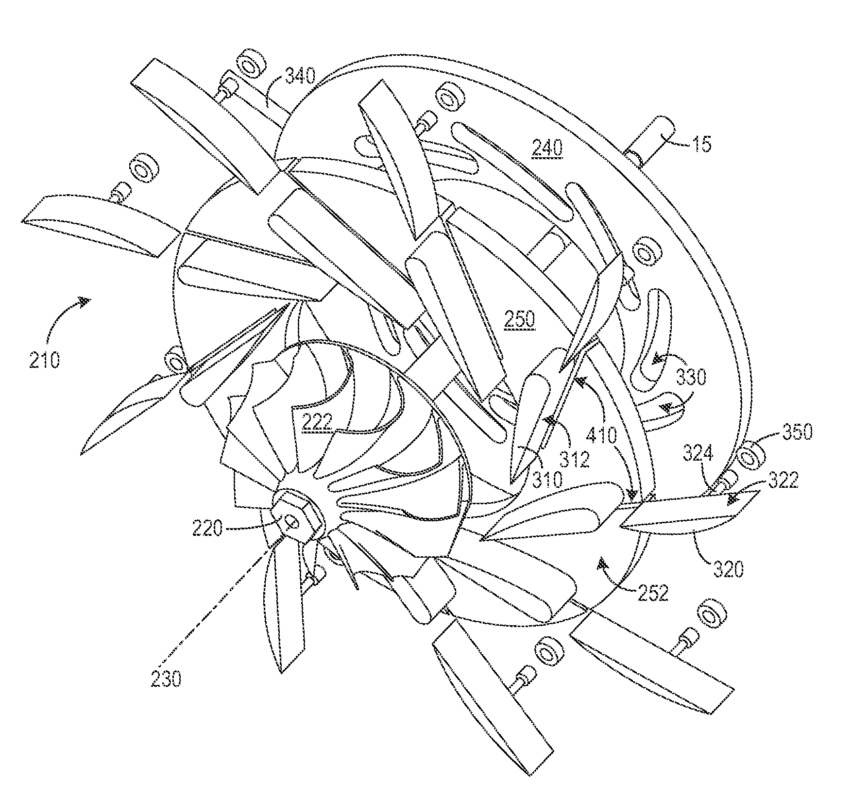
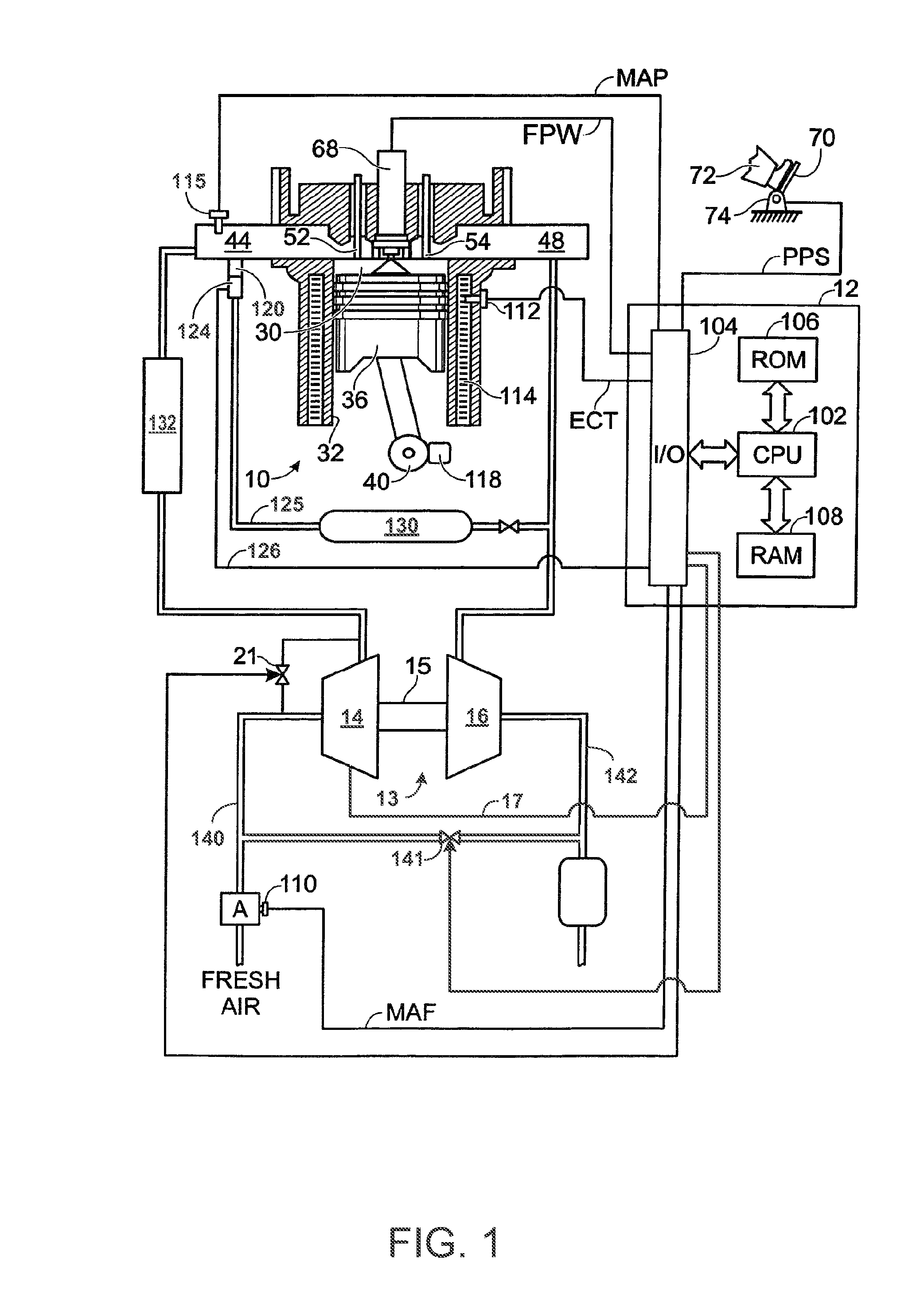
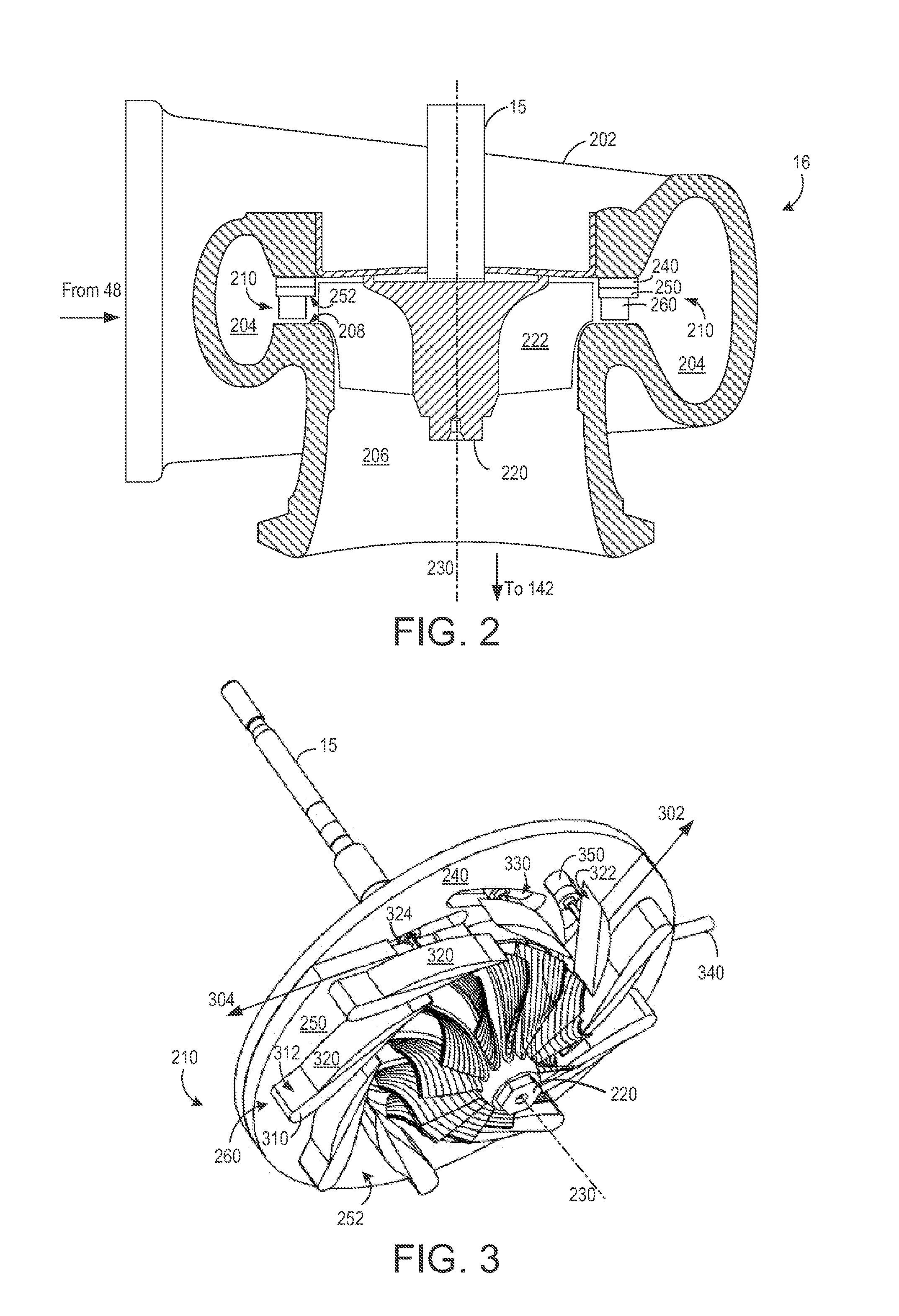
[0018]The following description relates to systems for variable geometry turbochargers of internal combustion engines. An example embodiment of an engine with a turbocharger is illustrated in FIG. 1. The example turbocharger includes a compressor driven by a turbine, such as the example embodiment of a turbine illustrated in FIG. 2. The example turbine includes a turbine nozzle and a turbine wheel, such as shown in more detail in FIGS. 3-6. FIG. 3 shows a perspective view of an example embodiment of a turbine nozzle and a turbine wheel. FIG. 4 shows an exploded view of an example embodiment of a turbine nozzle. FIGS. 5 and 6 show how a sliding nozzle vane of the turbine nozzle may be varied during different engine operating conditions. For example, decreasing the length of the sliding nozzle vane, as illustrated in FIG. 5, may be desirable when the engine is generating a large exhaust flow. As another example, increasing the length of the sliding nozzle vane, as illustrated in FIG. ...


PUM

PropertyMeasurementUnit
angleaaaaaaaaaa
angleaaaaaaaaaa
angleaaaaaaaaaa

Abstract

Various systems and methods are described for a variable geometry turbine. In one example, a turbine nozzle comprises a central axis and a nozzle vane. The nozzle vane includes a stationary vane and a sliding vane. The sliding vane is positioned to slide in a direction substantially tangent to an inner circumference of the turbine nozzle and in contact with the stationary vane.

Description

GOVERNMENT RIGHTS[0001]This invention was made with government support under DE-FC26-07NT43280 awarded by the Department of Energy. The government has certain rights in the invention.FIELD[0002]The present application relates to variable geometry turbines for turbochargers of internal combustion engines.BACKGROUND AND SUMMARY[0003]Engines may use a turbocharger to improve engine torque and / or power output density. In one example, a turbocharger may include a compressor and a turbine connected by a drive shaft, where the turbine receives exhaust gasses and the compressor receives intake air. In this way, the exhaust-driven turbine supplies energy to the compressor to boost the pressure and flow of air into the engine. For example, boost pressure may be increased by increasing the rotational speed of the turbine. The desired amount of boost may vary over operation of the engine. For example, the desired boost may be greater during acceleration than during deceleration.[0004]One soluti...

Claims


Application Information

Patent Timeline
Patent Type & Authority Patents(United States)
IPC IPC(8): F04D29/56F01D17/16F02D23/00F04D29/00F02B37/24
CPCF01D17/167F05D2220/40F02B37/24F05D2300/20Y02T10/144F05D2240/12F05D2230/90Y02T10/12
Inventor SUN, HAROLD HUIMINZHANG, JIZHONGHU, LIANGJUNHANNA, DAVE R.
Owner FORD GLOBAL TECH LLC
Why Eureka
Try Eureka