High recycling efficiency solid state light source device

a light source device and high recycling efficiency technology, applied in semiconductor devices for light sources, point-like light sources, lighting and heating devices, etc., can solve the problem and achieve the effect of reducing the light recycling efficiency of the device and large aberration

Active Publication Date: 2014-12-30
APPOTRONICS CORP LTD
View PDF11 Cites 0 Cited by
  • Summary
  • Abstract
  • Description
  • Claims
  • Application Information

AI Technical Summary

Benefits of technology

[0006]One problem that exists for the light source device shown in FIG. 13 is that, because the spherical reflector 23 has a relatively large aberration for large-angle lights, a significant portion of the large-angle light does not fall on the LED chip 21 after being reflected by the reflector 23, and therefore is not recycled. This reduces the light recycling efficiency of the device.
[0008]An object of the present invention is to increase the light recycling efficiency of LED light sources.

Problems solved by technology

One problem that exists for the light source device shown in FIG. 13 is that, because the spherical reflector 23 has a relatively large aberration for large-angle lights, a significant portion of the large-angle light does not fall on the LED chip 21 after being reflected by the reflector 23, and therefore is not recycled.
This reduces the light recycling efficiency of the device.

Method used


Image

  • High recycling efficiency solid state light source device
  • High recycling efficiency solid state light source device
  • High recycling efficiency solid state light source device

Examples


first embodiment

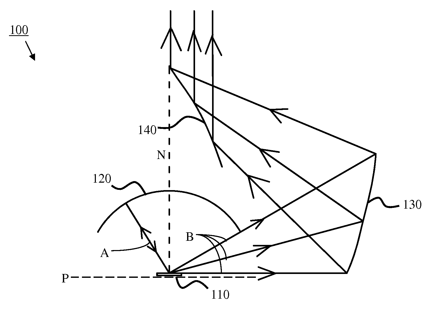
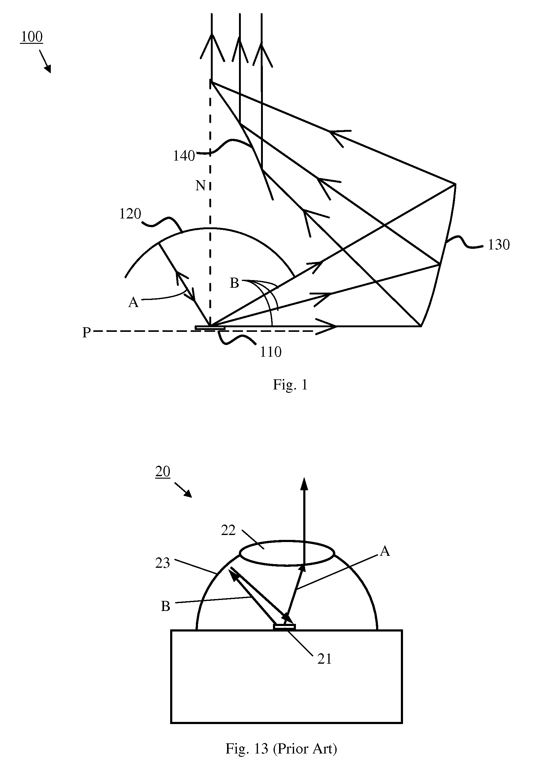
[0031]FIG. 1 illustrates a light source device according to the present invention. The light source device 100 includes a light source 110, a light recycling system and a light collection system. The light source 110 may be an LED chip. The LED chip may emit light of a desired color, such as UV, blue, green, red, IR, etc. The LED chip may also include wavelength conversion materials formed on its surface, which converts a shorter wavelength light (e.g., UV, blue, etc.) from the LED to a longer wavelength light (e.g. green, yellow, red, etc.). Preferably, the LED internally has a reflective surface below a light emitting material so that emitted light traveling in the downward direction in the drawing is reflected upwards to present it from being lost. The light recycling system includes a first reflector 120 having a spherical shape, which is disposed above the light source 110 and covers an area near the normal direction N (central axis) of the plane P defined by the light source 1...

fifth embodiment

[0045]FIG. 5 illustrates a light source device according to the present invention. The light source device 300 includes first and second light sources 310 and 312 each being an LED chip with wavelength conversion material formed thereon. The two wavelength conversion materials are selected such that they do not strongly absorb the converted light of each other. The two LED chips 310 and 312 are disposed in parallel such that the wavelength conversion materials face each other. A light recycling system, including a reflector 320 and a lens 321, is disposed between the two light sources (the second light source 312 may be considered a part of the light recycling system). The reflector 320, preferably a compound parabolic concentrator (CPC), is disposed around the second light source 312. The lens 321 is disposed near the output port of the reflector 320 to direct small-angle light from the first light source into the reflector 320. A light collection system includes a reflector 330, w...

eighth embodiment

[0053]FIG. 8 schematically illustrates a light source device according to the present invention. The light source device 400 includes two light sources, each being an LED chip 410 having wavelength conversion material 411 formed there on. The two LED chips 410 are disposed in parallel such that the wavelength conversion materials 411 face each other. A light recycling system includes a flat, double-sided reflector 450 disposed between and parallel to the two wavelength conversion materials 411. The reflector 450 reflects small-angle lights from each wavelength conversion material 411 back to itself, while reflect large-angle lights toward the side so that they exit from the space between the two LED chips 410. The double-sided reflector 450 may also be a double-sided scattering surface which scatters lights in all directions. A light collection system (not shown in FIG. 8) is provided around the LED chips 410 to collect and output the large-angle light. The light collection system m...


PUM


Abstract

A light source device includes a LED light source or a wavelength conversion material having a near Lambertian light emitting surface. The light source device includes a light recycling system to reflect small-angle lights (lights closer to the normal direction of the light emitting surface) back to the light source, and a collection system for collecting and outputting large-angle lights (lights farther away from the normal direction). The lights reflected by the light recycling system is scattered by the emitting surface in all directions, where the large-angle scattered lights are collected by the light collection system and the small-angle scattered light is reflected by the light recycling system again. A second excitation light source without wavelength conversion material or a second light source with its own wavelength conversion material may be provided, and the second light is directed to the light emitting surface by appropriate optical components.

Description

BACKGROUND OF THE INVENTION[0001]1. Field of the Invention[0002]This invention relates to solid state light source devices, and in particular, it relates to solid state light source device using light recycling to increase output brightness.[0003]2. Description of the Related Art[0004]Light emitting diodes (LEDs) have become a popular light source. However, the brightness of LED light sources is often insufficient for certain application areas such as large display devices, headlight for automobiles, stage lighting systems, etc. To improve the brightness of LED light sources, one approach is to increase the input power to each LED chip. But high power increases the demand on heat dissipation, because accumulated heat can cause the temperature of the LED chips to increase, reducing the light generating efficiency of the LED chips. This often results in an upper limit of the brightness of LED light sources. Moreover, large drive current can shorten the life of the LED devices and redu...

Claims


Application Information

Patent Timeline
Patent Type & Authority Patents(United States)
IPC IPC(8): F21V5/02F21V7/05F21V13/14F21Y101/02F21V7/06F21V9/16F21V7/04F21V7/00
CPCF21V7/05F21V7/06F21V7/045F21V9/16F21V7/0041F21Y2101/02F21V5/02F21V7/0008F21V13/14F21V7/0025F21K9/56F21V7/0033F21V13/08F21K9/64F21Y2115/10F21V9/38
Inventor HU, FEILI, YIYANG, YI
Owner APPOTRONICS CORP LTD
Why Eureka
Try Eureka