
Golf ball and method of manufacturing a golf ball

a manufacturing method and golf ball technology, applied in the field of golf balls and methods of manufacturing golf balls, can solve the problems of compromising the integrity and affecting the performance of the ball, and causing the ball to be skewed

Inactive Publication Date: 2014-12-30
NIKE INC
View PDF420 Cites 30 Cited by
  • Summary
  • Abstract
  • Description
  • Claims
  • Application Information

AI Technical Summary

Benefits of technology

The patent describes a multi-layer golf ball with a thermoplastic resin cover that has a hardness gradient, with the outer part having a higher hardness than the inner part. This hardness gradient can be achieved by using an isocyanate solution that includes an isocyanate compound, a co-reactant compound, and a catalyst. The reaction between the isocyanate compound and the co-reactant compound forms a reaction product that modifies the physical properties of the outer part of the cover. This modification results in a microindentation hardness that is greater than the hardness of the inner part. The technical effect of this patent is the creation of a multi-layer golf ball with a unique hardness gradient that provides improved performance and durability.

Problems solved by technology

For long distance shots, where drivers, woods, and long irons are used, high spin is generally not desirable.
High spin can increase lift which can result in a loss of distance.
However, soft covers are susceptible to “scuffing” or shear yielding of the polymer that compromises the integrity and performance of the ball.
These shear forces are high enough to cause the polymer material of the cover to shear yield or “scuff.” A high degree of scuffing renders the ball unfit for play.
It can also cause the spin rate to decrease during the shot when the scuffing occurs, thus giving inconsistent spin characteristics to the golf ball.
Nonetheless, scuffing continues to be problem.

Method used


Image

  • Golf ball and method of manufacturing a golf ball
  • Golf ball and method of manufacturing a golf ball
  • Golf ball and method of manufacturing a golf ball

Examples


Embodiment Construction

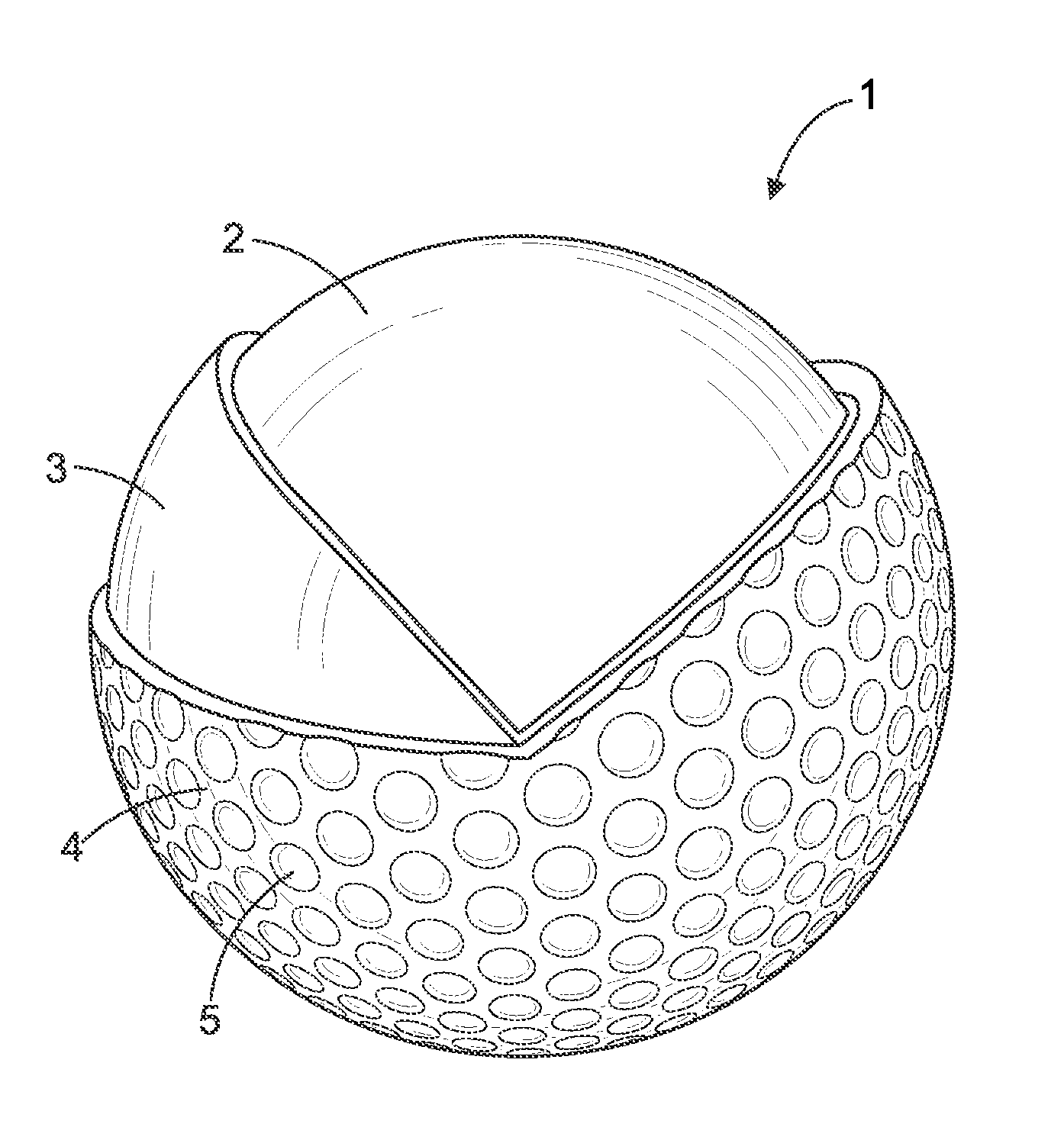
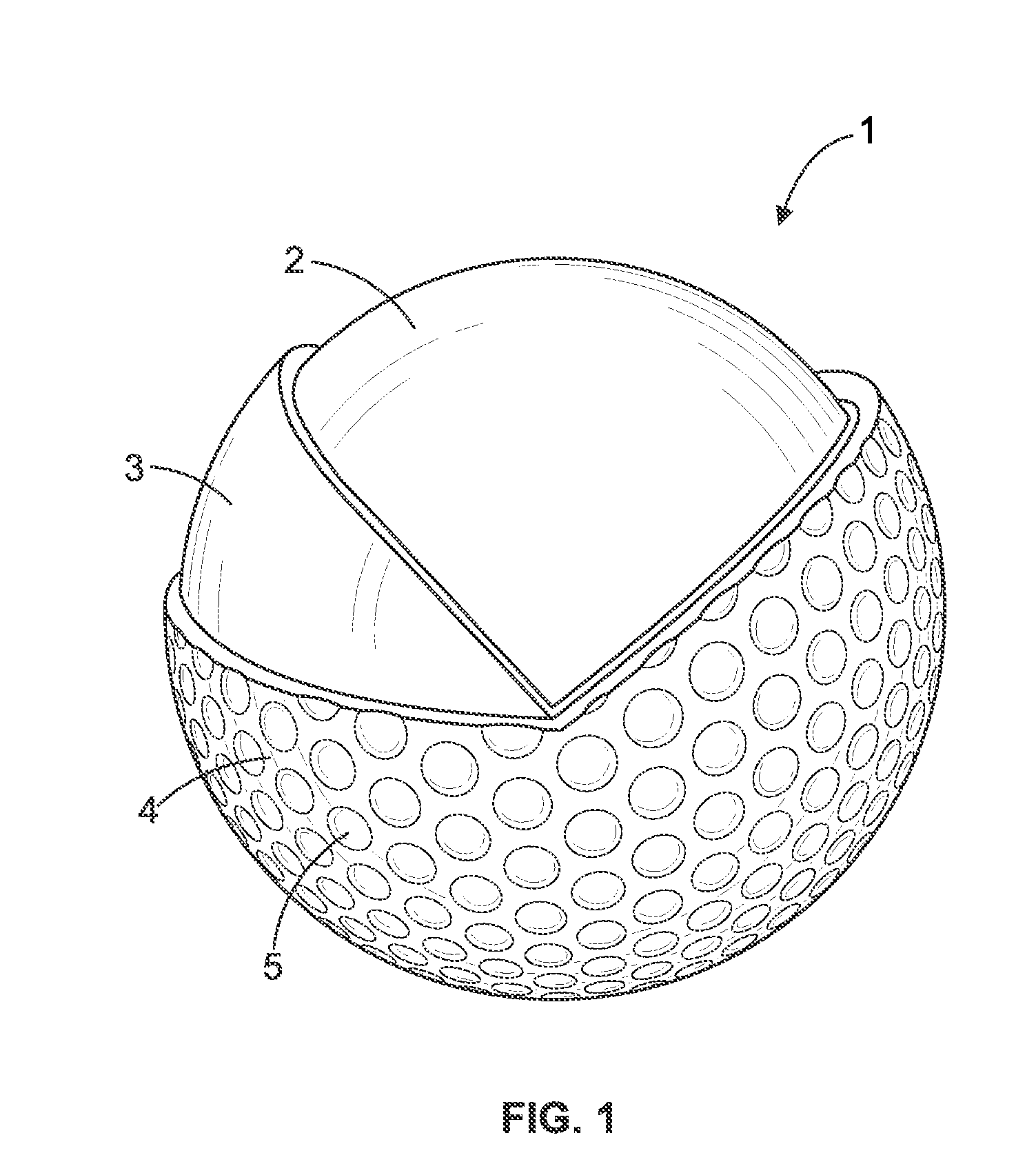
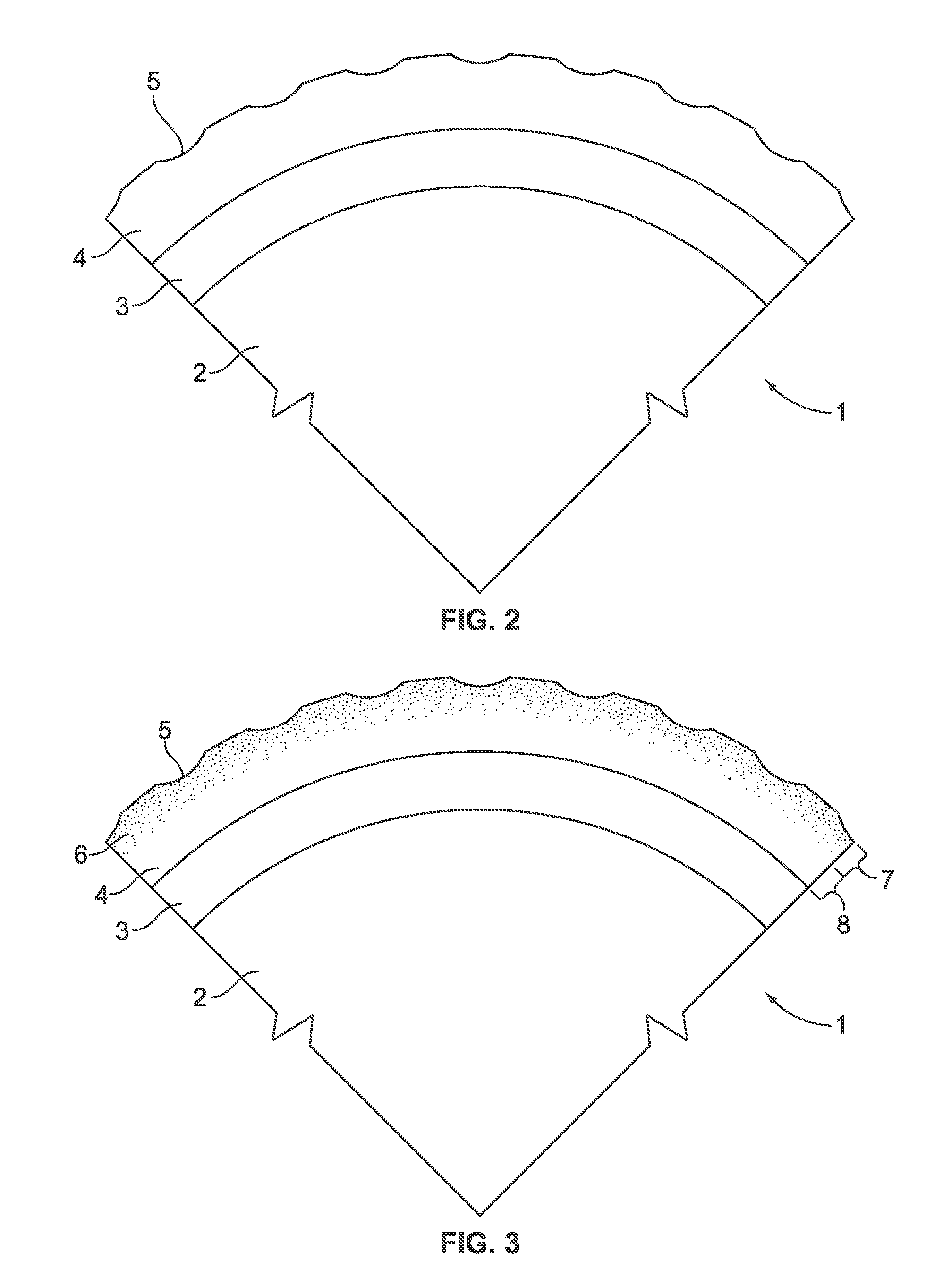
[0012]An embodiment of the current invention can be useful, for example, to improve the performance of multilayer golf balls. As used herein, the term multi-layer golf ball means a golf ball constructed of at least two layers and can include, for example, two-piece, three-piece, and four-piece golf balls. Referring to FIGS. 1 through 3, an example of a three-piece multi-layer golf ball can include a core 2, an intermediate layer 3, and a cover 4. The cover 4 can include dimples 5 molded thereon. Multilayer golf balls and corresponding individual layers of the ball may be made by any suitable materials and methods known to those of ordinary skill in the art, including those described in, for example, U.S. Pat. No. 7,491,878.

[0013]In one embodiment of the current invention, a golf ball with cover formed of thermoplastic resin, such as thermoplastic polyurethane, is permeated with an isocyanate solution. The solution can include an isocyanate compound, a co-reactant compound, and a cat...


PUM

PropertyMeasurementUnit
thicknessaaaaaaaaaa
temperatureaaaaaaaaaa

Abstract

A golf ball and a method of manufacturing a golf ball is disclosed. In one embodiment, a method of manufacturing a golf ball includes molding a cover made of thermoplastic resin over at least one intermediate layer of a golf ball; permeating an isocyanate solution comprising an isocyanate compound and a co-reactant compound into an outer portion of the cover; and permeating a catalyst into the outer portion of the cover. The catalyst catalyzes a reaction between the isocyanate compound and the co-reactant compound to form a reaction product. The co-reactant compound can be a second isocyanate compound, the catalyst can be a quaternary ammonium salt, and the reaction product can be isocyanurate. The reaction product modifies at least one physical property of the outer portion such that the physical property of the outer portion is different than the physical property of the inner portion. The modified physical property can be microindentation hardness, where the microindentation hardness of the outer portion is greater than the microindentation hardness of an inner portion of the cover.

Description

CROSS-REFERENCE TO RELATED APPLICATIONS[0001]This application claims the benefit of U.S. Provisional Application Nos. 61 / 366,183, filed Jul. 21, 2010 and 61 / 370,096, filed Aug. 2, 2010, which are incorporated by reference in their entireties as if fully set forth herein.FIELD AND BACKGROUND OF THE INVENTION[0002]This invention relates to golf balls and methods of manufacturing golf balls. The physical properties, composition, and design of a golf ball determine its performance characteristics during play, including distance, loft, flight symmetry, spin, and durability. Golf balls can be constructed so that certain performance characteristics are emphasized and / or deemphasized to execute various types of shots in view of the different golf clubs used to make such shots.[0003]For example, golf balls can be constructed to emphasize or deemphasize the spin characteristic of the ball according to the distance of the desired shot and the club used to make such shot. For long distance shot...

Claims


Application Information

Patent Timeline
Patent Type & Authority Patents(United States)
IPC IPC(8): A63B37/00A63B37/04C08G18/02C08G18/18
CPCC08G18/1875A63B37/0031A63B37/0043A63B37/0033A63B37/0092A63B37/0075C08G18/022A63B37/0022
Inventor KENNEDY, III, THOMAS, J.
Owner NIKE INC
Learn More