Sediment monitoring system for stormwater management facilities

a sediment monitoring and stormwater management technology, applied in the field of sensors, can solve the problems of complex measurement of stormwater sediment levels, sensors not adapted to measuring the level of heterogeneous sludge or slurry, and accumulation of solids in stormwater management facilities,

Inactive Publication Date: 2014-12-30
DECKER THOMAS R
View PDF15 Cites 5 Cited by
  • Summary
  • Abstract
  • Description
  • Claims
  • Application Information

AI Technical Summary

Problems solved by technology

Over time, the suspended solids accumulate in the stormwater management facilities and require cleaning.
While a number of sensors are available for measuring the level of liquids or solids in a container, these sensors are not adapted to measuring the level of a heterogeneous sludge or slurry of the kind that often accumulates in stormwater facilities.
Adding to the complexity of measuring stormwater sediment levels is the frequent presence of floating debris and / or oil.
Since these devices depend upon the buoyancy of the float in liquid, they are not adaptable to monitoring the level of a solid or semi-solid sediment or sludge.
Such contact-based systems have limited accuracy and life cycles due to their moving parts, and they are not well suited to semi-fluid sludges.
Since the Snelling sensor is based on the larger difference in thermal conductivity between liquid and vapor phases, it is not readily adaptable to detecting a liquid / solid or air / solid interface.
There are two particular problems encountered in measuring the sediment level in a stormwater management facility: (1) the sediment layer is often mixed with and / or suspended in a layer of residual stormwater, such that the liquid / solid interface is not well defined, and (2) floating solid debris is usually present in the stormwater, further obscuring the liquid / solid boundary.

Method used


Image

  • Sediment monitoring system for stormwater management facilities
  • Sediment monitoring system for stormwater management facilities
  • Sediment monitoring system for stormwater management facilities

Examples


Embodiment Construction

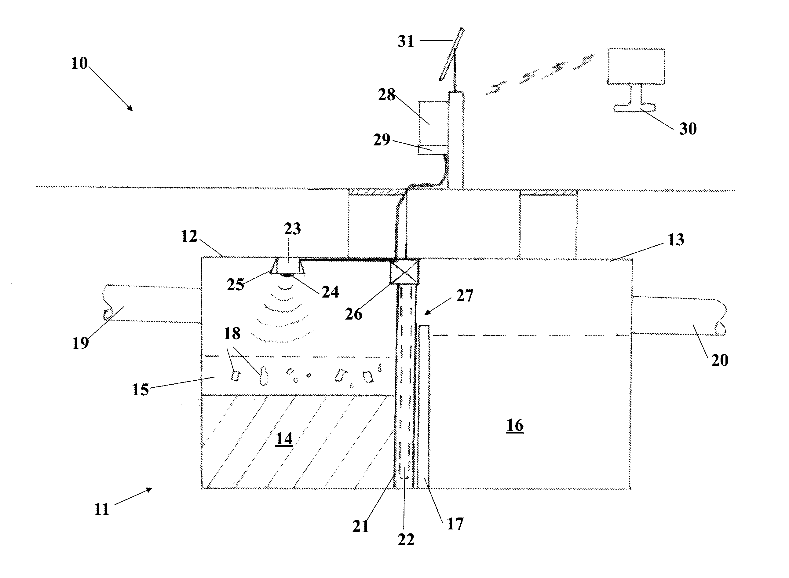
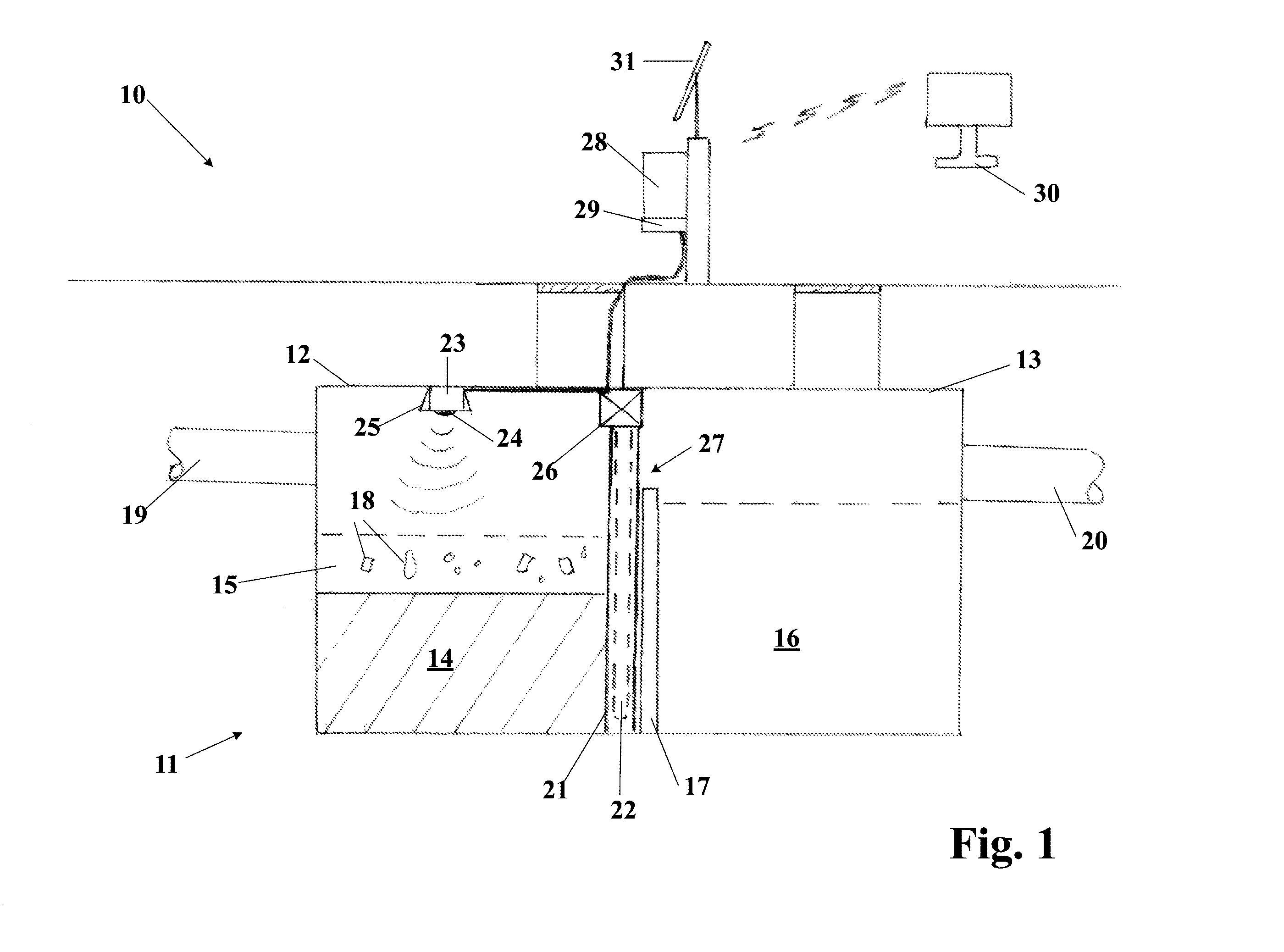
[0021]Referring to FIG. 1, the preferred embodiment of the sediment monitoring system 10 is shown installed in a typical underground two-chamber stormwater setting tank 11. In the first chamber of the tank 12, a layer of sediment 14 accumulates at the bottom of the tank, frequently with a layer of water or slurry 15 above it, which may contain floating debris 18. The second chamber of the tank 13 contains cleaner stormwater 16 that has flowed over the central tank baffle 17. Untreated stormwater enters the tank 11 through an inflow pipe 19 into the first chamber 12, and treated stormwater leaves the tank 11 through an outflow pipe 20 from the second chamber 13.

[0022]A capacitive sensor rod 21, comprising multiple capacitive elements 22, extends downward within the first chamber of the tank 12 into the sediment layer 14. A downward-pointing ultrasonic transponder 23, comprising a transmitting unit 24 and a receiving unit 25, is located near the top of the first chamber of the tank 12...


PUM


Abstract

A dual sensor sediment monitoring system for stormwater management facilities includes a capacitive sensor and an ultrasonic sensor. The former periodically determines if a liquid layer exists above the sediment and activates the ultrasonic sensor when it does not. The echo delay measured by the ultrasonic sensor is used to calculate the sediment level, which is wirelessly transmitted to a remote computer for database compilation and use in scheduling maintenance involving sediment removal.

Description

BACKGROUND OF THE INVENTION[0001]The present invention relates to the general field of sensors for measuring the level of material in a container, and more particularly to the means for remotely monitoring the level of sediment that accumulates within stormwater management facilities.[0002]Stormwater management facilities, including detention basins and manufactured treatment devices, are installed to capture suspended solids in stormwater in order to improve water quality. Over time, the suspended solids accumulate in the stormwater management facilities and require cleaning. In the absence of a sensor system for measuring the accumulated sediment level, maintenance personnel must periodically physically access the facilities to view sediment levels.[0003]While a number of sensors are available for measuring the level of liquids or solids in a container, these sensors are not adapted to measuring the level of a heterogeneous sludge or slurry of the kind that often accumulates in st...

Claims


Application Information

Patent Timeline
Patent Type & Authority Patents(United States)
IPC IPC(8): G01F23/26G01F17/00
CPCG01F23/0076G01F23/296G01F23/2962G01F23/263G01F23/0069G01F23/802G01F23/804
Inventor DECKER, THOMAS, R.
Owner DECKER THOMAS R
Why Eureka
Try Eureka