Method of clamping a substrate and clamp preparation unit
a substrate and preparation unit technology, applied in the direction of metal-working holders, positioning apparatuses, supports, etc., can solve the problems of substrate clamping mechanism, unsuitable use solution, and ineffective clamping mechanism, and achieve the effect of improving performan
- Summary
- Abstract
- Description
- Claims
- Application Information
AI Technical Summary
Benefits of technology
Problems solved by technology
Method used
Image
Examples
first embodiment
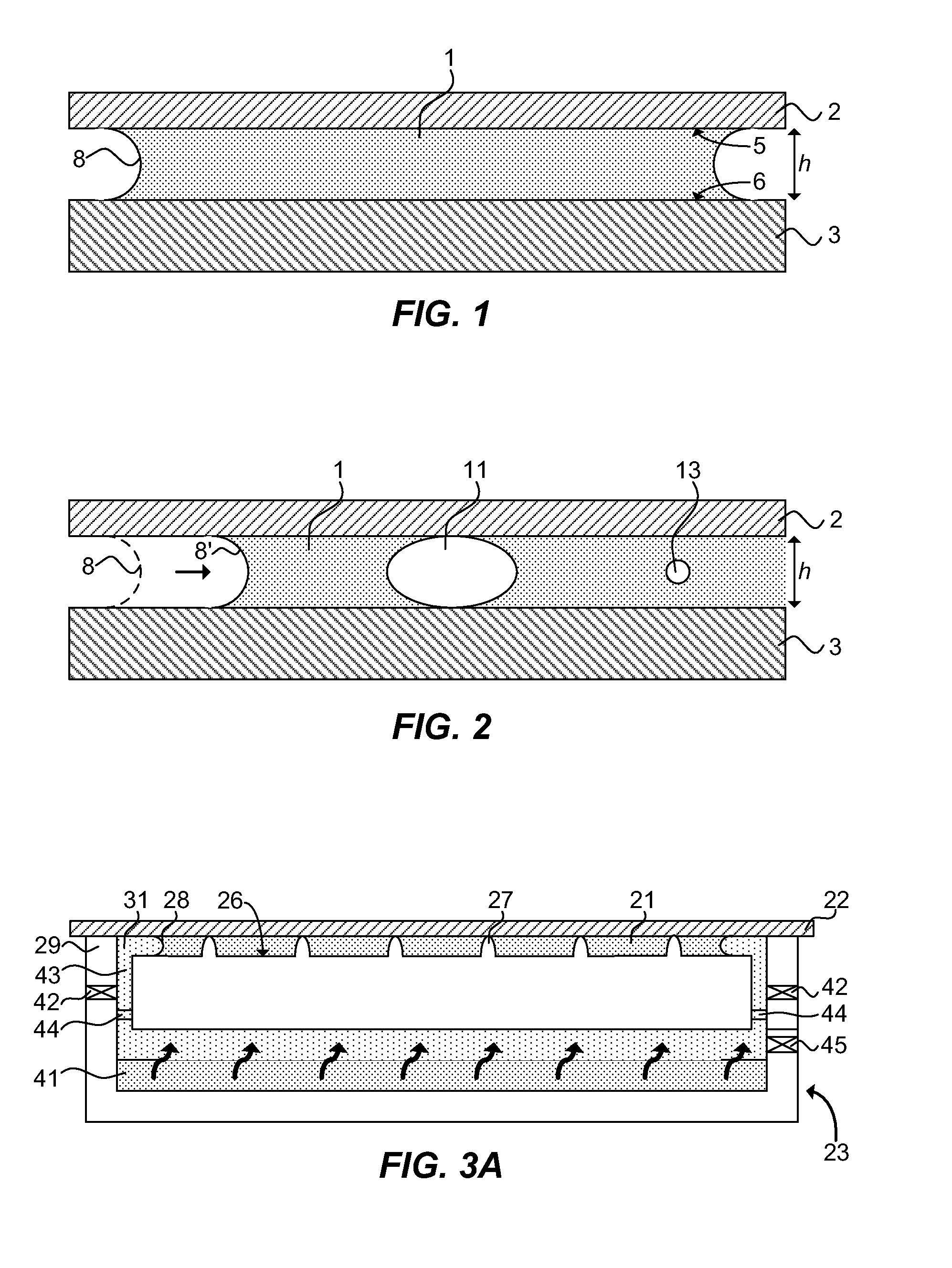
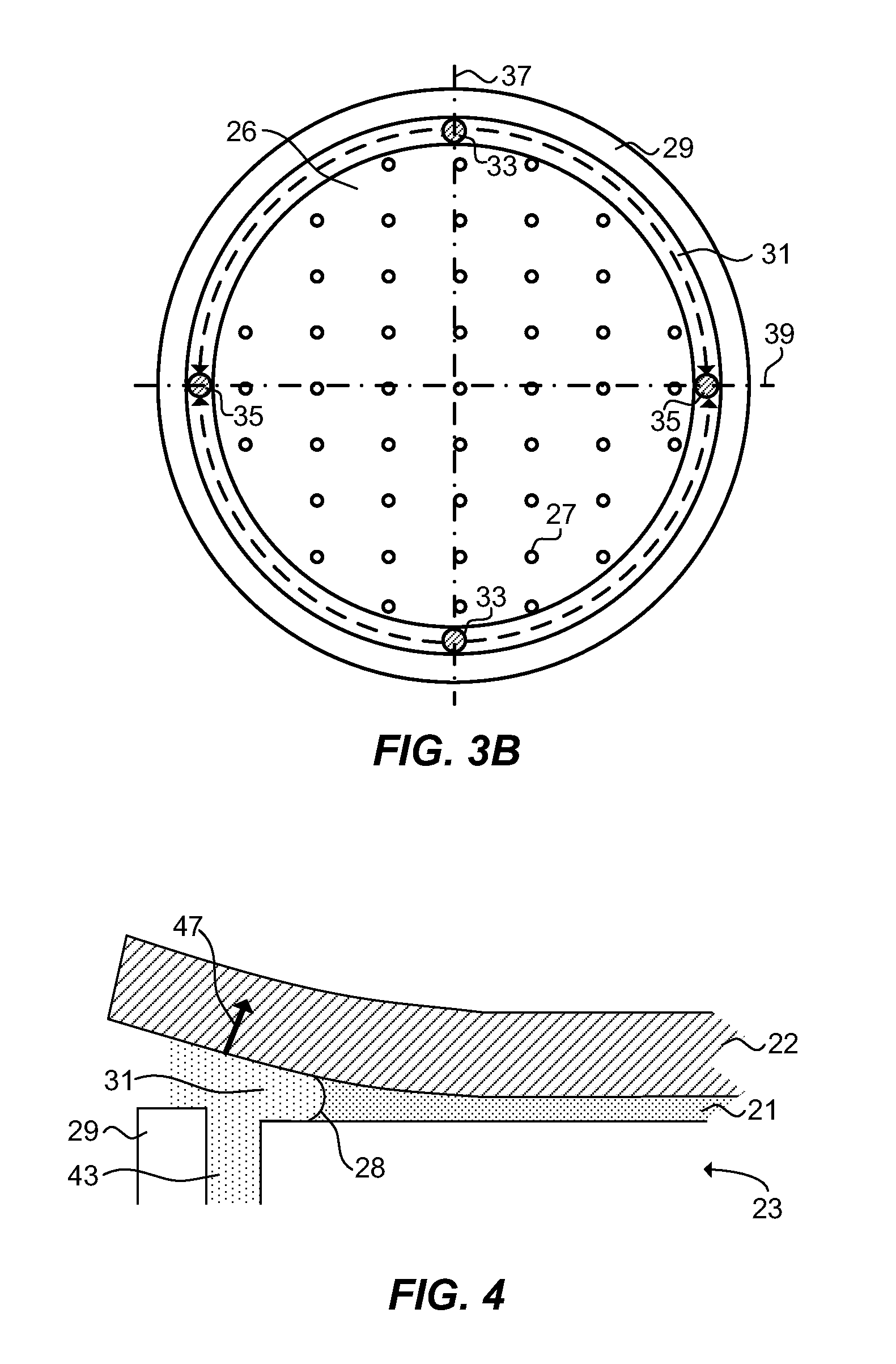
[0037]FIGS. 3A and 3B are a sectional view and a top view of a substrate support structure 23 supporting a substrate according to the invention respectively. The support structure is equipped to clamp a substrate 22 by means of a capillary layer 21. The surface 26 of the substrate support structure 23 is provided with a plurality of contact elements 27 in the form of burls. The substrate support structure 23 further comprises a sealing structure 29 and a liquid removal system.
[0038]In addition to or instead of using burls as contact elements 27, a plurality of spacers, e.g. glass grains, SiO2 grains or the like may be dispersed uniformly over the surface 26 of the substrate support structure 23. The presence of contact elements like burls may reduce the influence of contamination by particles on the backside of the substrate 22. Furthermore, the contact elements serve the purpose of keeping the substrate 22 substantially flat by withstanding the clamping force of the capillary layer...
second embodiment
[0054]FIG. 5 is a sectional view of a substrate support structure 23 supporting a substrate 22 according to the invention. The embodiment of the substrate support structure 23 of FIG. 5 further comprises a circumferential rim 51. The circumferential rim 51 provides a smaller distance between the substrate support structure 23 and the substrate 22. While the nominal distance between the substrate support structure 23 and the substrate 22, in FIGS. 1 and 2 referred to as height h, typically is about 3-10 microns, the distance between the circumferential rim 51 and the substrate 22 typically would lie in the range of 500 nm to 1.5 microns. Preferably, the circumferential rim 51 has a height being less than 1 micron smaller than the nominal height of contact elements provided on the surface 26 of the substrate support structure 23.
[0055]Without wishing to being bound by theory, the circumferential rim 51 is believed to limit substrate peeling in a way described with reference to FIGS. 6...
third embodiment
[0075]FIG. 8 schematically shows a top view of a substrate support structure 83 according to the invention. The substrate support structure 83 comprises a surface 86 for clamping a substrate. Preferably, the surface is provided with contact elements 87. Additionally, the substrate support structure comprises a gas distribution system including a moat 91, gas inlets 93, and gas outlets 95. Functions of these components have been discussed with reference to FIG. 3A and equally apply for this embodiment. The substrate support structure 83 may be used in embodiments of the method of clamping in a similar way as discussed with respect to substrate support structure 23 with reference to FIGS. 7A-7J.
[0076]In contrast to embodiments of the substrate support structure 23 shown in FIGS. 3A and 5, substrate support structure 83 comprises a surface 86 which is divided in a plurality of sub-surfaces. The sub-surfaces may take the form of tiles, for example of hexagonal shape, and be arranged in ...
PUM
| Property | Measurement | Unit |
|---|---|---|
| Fraction | aaaaa | aaaaa |
| Angle | aaaaa | aaaaa |
| Time | aaaaa | aaaaa |
Abstract
Description
Claims
Application Information
 - R&D
- Intellectual Property
- Life Sciences
- Materials
- Tech Scout
- Unparalleled Data Quality
- Higher Quality Content
- 60% Fewer Hallucinations
Browse by: Latest US Patents, China's latest patents, Technical Efficacy Thesaurus, Application Domain, Technology Topic, Popular Technical Reports.
© 2025 PatSnap. All rights reserved.Legal|Privacy policy|Modern Slavery Act Transparency Statement|Sitemap|About US| Contact US: help@patsnap.com


