Cleaning apparatus and liquid ejection apparatus and cleaning method

a technology of liquid ejection and cleaning apparatus, which is applied in the direction of printing, inking apparatus, etc., can solve the problems of large movement mechanism, long cleaning time, and failure of ejection, so as to improve the cleaning effect of the nozzle surface, prevent the possibility of ejection defects of the liquid ejection head, and improve the reliability of ejection

Inactive Publication Date: 2010-08-26
FUJIFILM CORP
View PDF2 Cites 36 Cited by
  • Summary
  • Abstract
  • Description
  • Claims
  • Application Information

AI Technical Summary

Benefits of technology

[0013]According to the present invention, the nozzle surface cleaning effect is improved, ejection defec

Problems solved by technology

In an inkjet head, if dust or liquid of increased viscosity, or the like, adheres to the interior or the periphery of the nozzle apertures through which liquid droplets are ejected, then the ejection direction of the liquid droplets is deflected and displacement of the landing position occurs, and the nozzles become blocked, leading to ejection failures.
However, in this method, ink between the nozzle plate and the cleaning plate is collected to remove the ink droplets and dust adhering to the nozzle surface in a state where the cleaning plate is stationary, and therefore when used in a line head

Method used


Image

  • Cleaning apparatus and liquid ejection apparatus and cleaning method
  • Cleaning apparatus and liquid ejection apparatus and cleaning method
  • Cleaning apparatus and liquid ejection apparatus and cleaning method

Examples


first embodiment

of Cleaning Apparatus

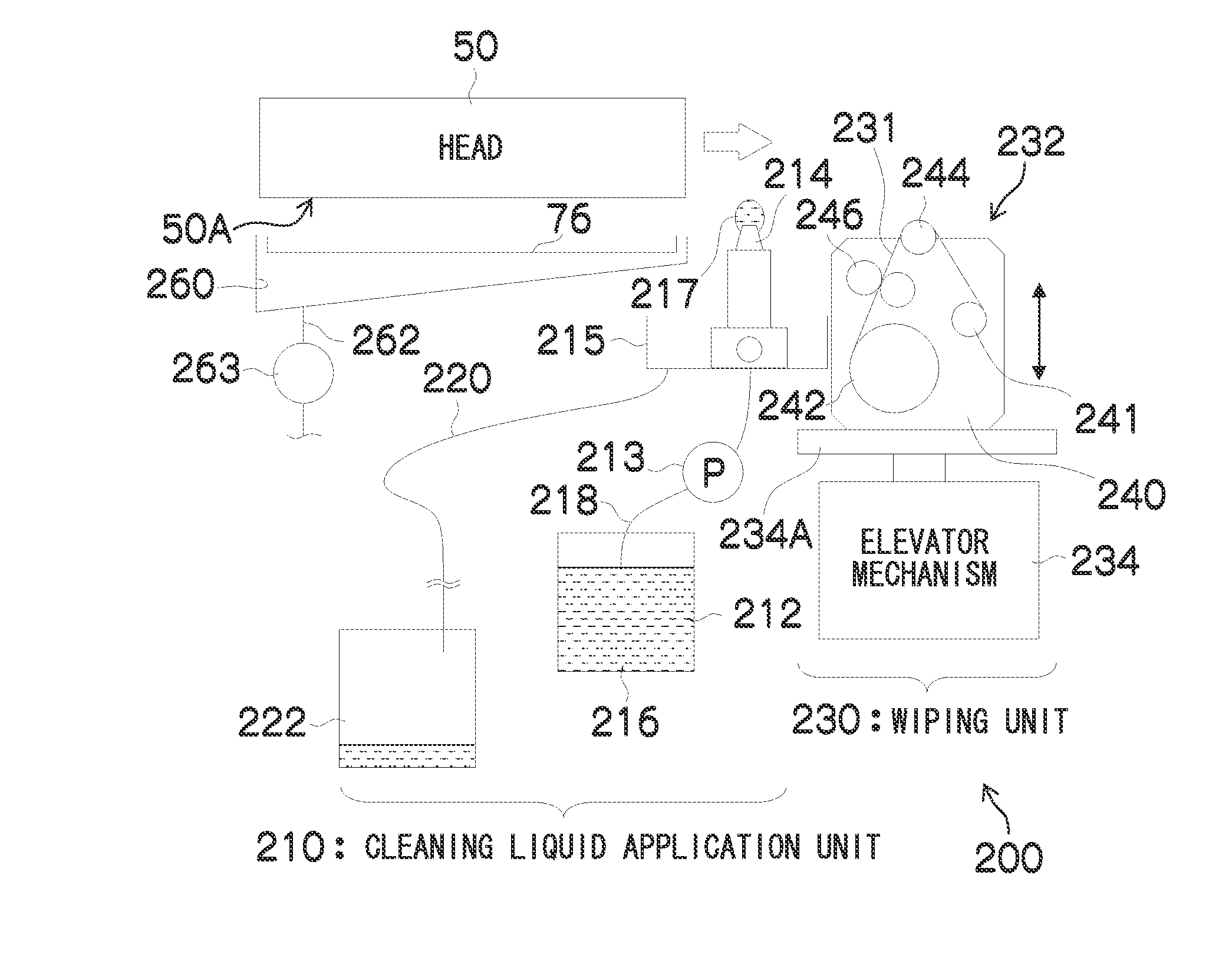
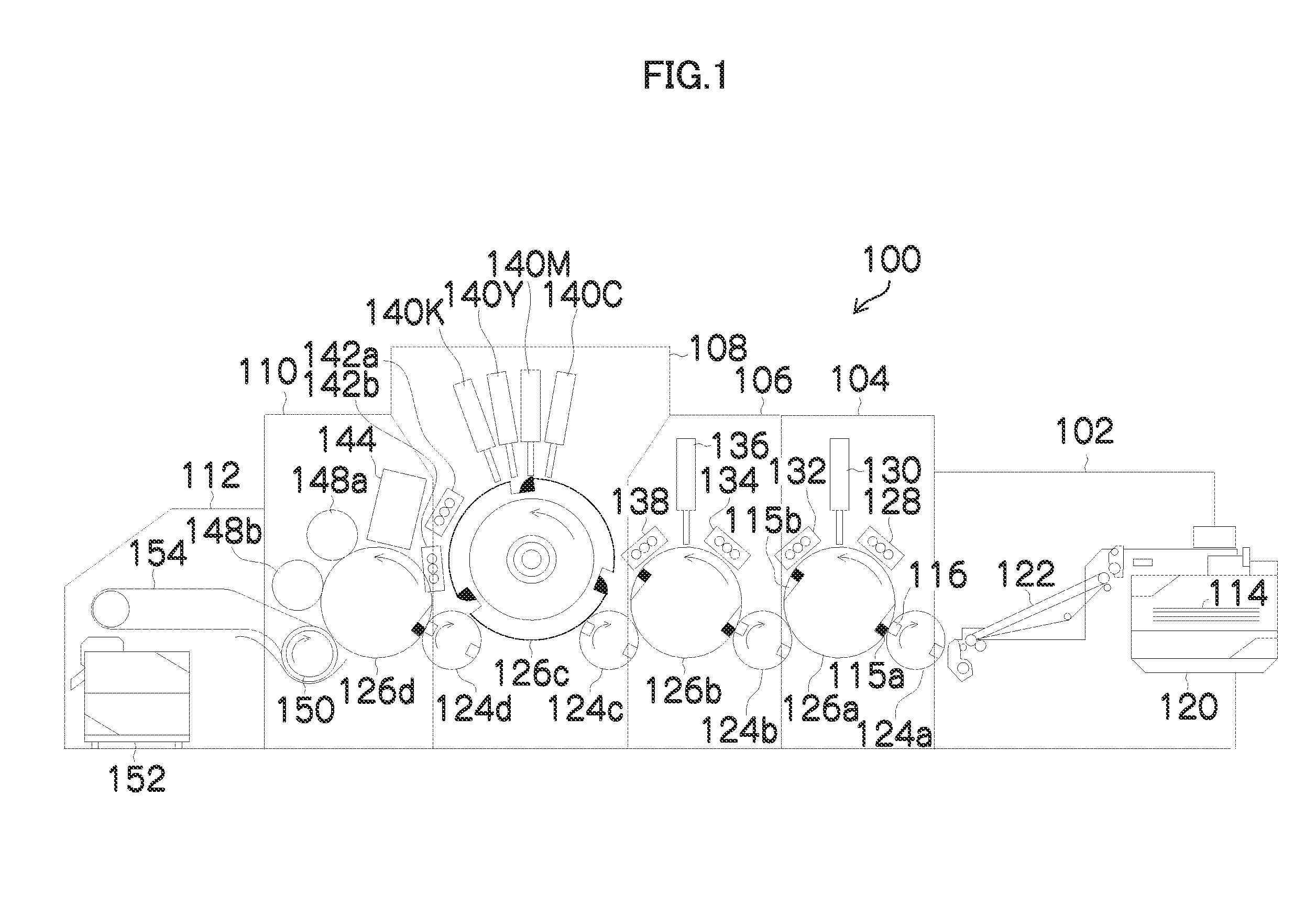
[0081]FIG. 7 is a diagram showing the composition of a cleaning apparatus 200, which is employed in the maintenance unit 70, according to an embodiment of the present invention. Here, the head 50 is described as the representative of the ink ejection heads 140C, 140M, 140Y and 140K.

[0082]The cleaning apparatus 200 is provided with a cleaning liquid application unit 210, which corresponds to the cleaning liquid application unit 74 in FIG. 6, and a wiping unit 230, which corresponds to the wiping unit 72 in FIG. 6. The cleaning liquid application unit 210 includes a cleaning liquid tank 212, a cleaning liquid pump 213, a cleaning liquid nozzle 214 and a used liquid receptacle 215. As the cleaning liquid 216, a special liquid having higher cleaning effects than the liquid (ink) that is ejected from the head 50 is used. For example, it is possible to use a cleaning liquid containing a solvent, such as DEGmBE (diethylene glycol monobutyl ether) as the cleaning liquid...

first example

[0103]The wiping trace could be removed when the head movement speed was 20 mm / sec, the clearance between the head nozzle surface and the cleaning liquid nozzle (the gap between the top end of the cleaning liquid nozzle and the head nozzle surface) was 1 mm, the diameter of the cleaning liquid nozzle was 1 mm, and the finishing rinse was carried out using a cleaning liquid having a main component of DEGmBE.

second embodiment

of Cleaning Apparatus

[0104]In the first embodiment described above, in the finishing rinse, the cleaning liquid pillar 217 is formed from the cleaning liquid nozzle 214 to create a liquid pool between the cleaning liquid nozzle 214 and the nozzle surface 50A, and the head 50 is moved at a slow speed so as not to break down the meniscus. On the other hand, in the cleaning apparatus according to the second embodiment, it is possible to spout the cleaning liquid toward the nozzle surface 50A from the cleaning liquid nozzle 214 while the head 50 is moved.

[0105]In this case, the cleaning liquid is continuously supplied to the nozzle surface 50A, and the cleaning liquid of the meniscus that is in contact with the nozzle surface 50A is constantly replaced with new liquid, and therefore the cleaning capabilities of the cleaning liquid are maintained and further improvement of the cleaning capabilities can be achieved.

[0106]Even in a case where the cleaning liquid is made to continuously flo...


PUM


Abstract

The cleaning apparatus cleans a nozzle surface of a liquid ejection head. The cleaning apparatus includes: a cleaning liquid supply device which supplies cleaning liquid to the nozzle surface while being not in contact with the nozzle surface; a liquid layer formation control device which causes the cleaning liquid supply device to supply a prescribed amount of the cleaning liquid to form a layer of the cleaning liquid that fills in a space between the cleaning liquid supply device and the nozzle surface; and a movement control device which controls a movement device so as to move the cleaning liquid supply device and the liquid ejection head relatively to each other at a relative speed in which a meniscus is not broken down, the meniscus being of the layer of the cleaning liquid in a portion of the layer of the cleaning liquid that makes contact with the nozzle surface.

Description

BACKGROUND OF THE INVENTION[0001]1. Field of the Invention[0002]The present invention relates to a cleaning apparatus, a liquid ejection apparatus and a cleaning method, and more particularly, to head cleaning technology for cleaning a nozzle surface (ejection surface) in a liquid ejection head based on an inkjet system.[0003]2. Description of the Related Art[0004]In an inkjet head, if dust or liquid of increased viscosity, or the like, adheres to the interior or the periphery of the nozzle apertures through which liquid droplets are ejected, then the ejection direction of the liquid droplets is deflected and displacement of the landing position occurs, and the nozzles become blocked, leading to ejection failures. In order to prevent or restore ejection defects of this kind, an inkjet recording apparatus having a mechanism for cleaning the nozzle surface is known.[0005]Japanese Patent Application Publication No. 2005-096125 describes an inkjet recording apparatus which cleans the no...

Claims


Application Information

Patent Timeline
IPC IPC(8): B41J2/165
CPCB41J2/16552B41J2202/21B41J2/16585
Inventor INOUE, HIROSHI
Owner FUJIFILM CORP
Why Eureka
Try Eureka