
Cleaning appliance

a vacuum cleaning and utensil technology, applied in the field of utensil cleaning, can solve the problems of undesirable flex in vacuum cleaning devices, and the degree of lateral flex between, and achieve the effects of reducing flex, reducing flex, and reducing flex

Active Publication Date: 2015-01-06
DYSON TECH LTD
View PDF6 Cites 69 Cited by
  • Summary
  • Abstract
  • Description
  • Claims
  • Application Information

AI Technical Summary

Benefits of technology

The invention allows a vacuum cleaner's bin to be opened and removed using a single user-operated interface. This is useful for handheld cleaning apparatuses where the separating apparatus needs to be emptied when attached to the main body. The use of the same actuator for both functions simplifies the user interface and makes the product lighter and space efficient.

Problems solved by technology

However, a disadvantage with this arrangement is that there is a degree of ‘lateral flex’ between the main body and the cyclonic separator which may be noticeable particularly when a significant sideways load is exerted on the dirty air inlet of the cyclonic separator.
Flex in a vacuum cleaning device is generally undesirable since it may be perceived by a user as an area of mechanical weakness, or simply an indicator of low quality.

Method used


Image

  • Cleaning appliance
  • Cleaning appliance
  • Cleaning appliance

Examples


Embodiment Construction

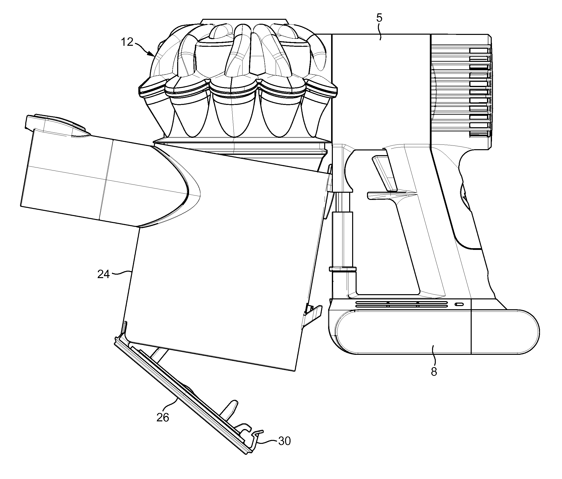
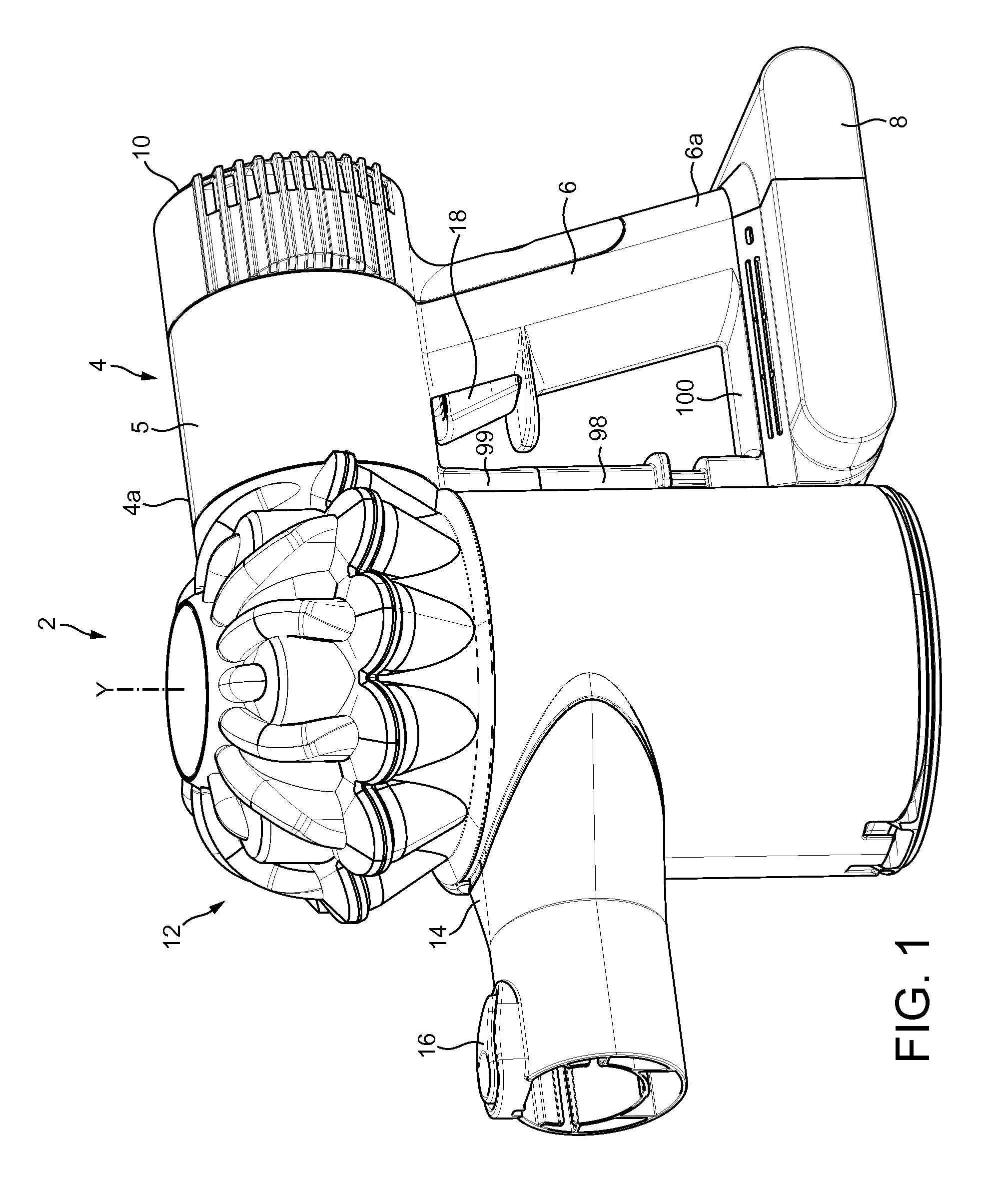
[0038]With reference to FIGS. 1 and 2, a handheld vacuum cleaner 2 has a main body 4 which houses an airflow generator 5 in the form of a motor and fan unit above a generally upright handle or grip portion 6. The handle 6 has a lower end 6a that supports a generally slab-like battery pack 8. A set of exhaust vents 10 are provided on the main body 4 for exhausting air from the handheld vacuum cleaner 2.

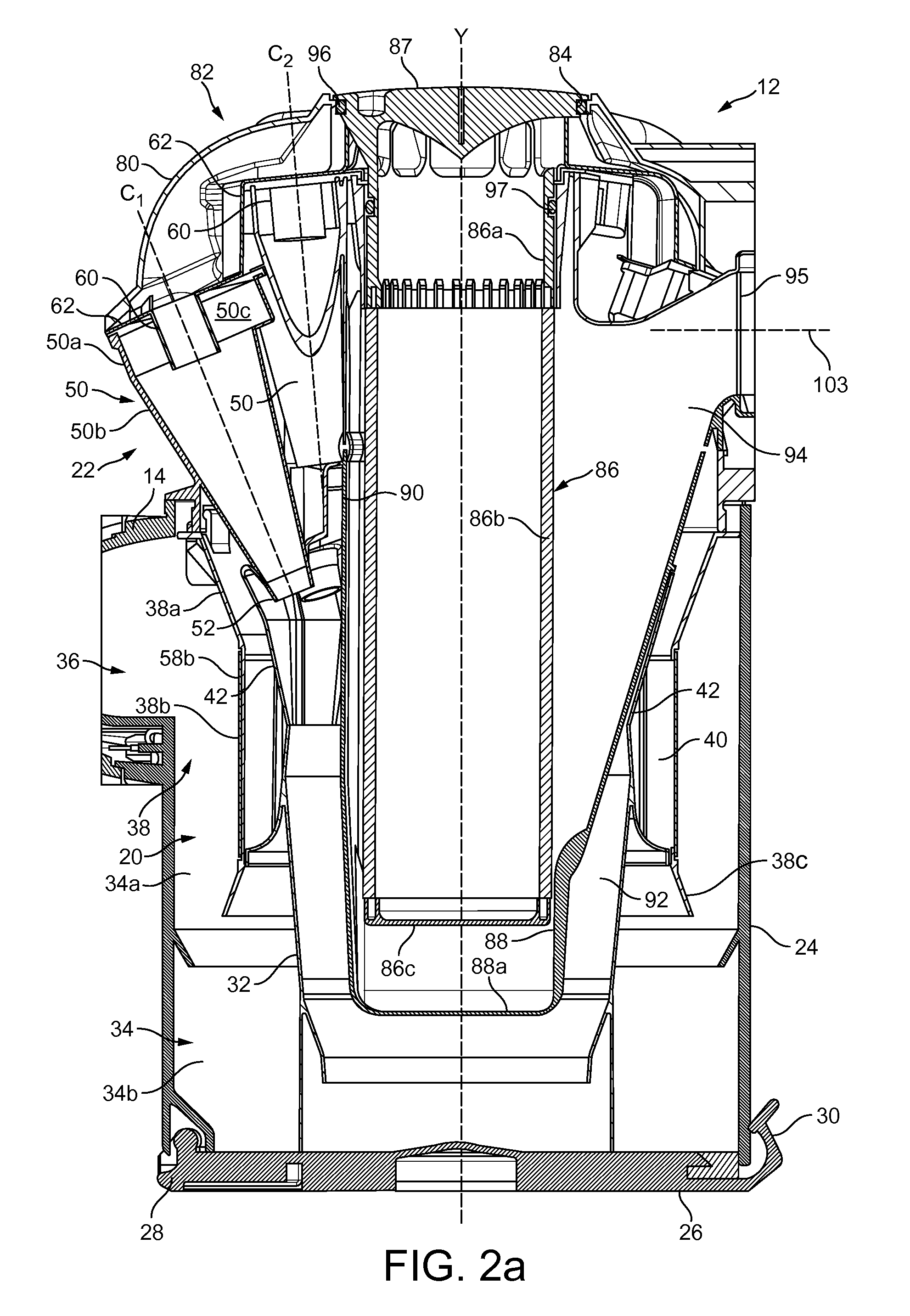
[0039]The main body 4 supports a cyclonic separating apparatus 12 that is operable to remove dirt, dust and other debris from a dirt-bearing airflow drawn into the vacuum cleaner by the airflow generator. The cyclonic separator 12 is attached to a forward part 4a of the main body 4 and an air inlet nozzle 14 extends from a forward portion of the cyclonic separator that is remote from the main body 4. The air inlet nozzle 14 is configured so that a suitable brush tool can be removably mounted to it and includes a catch 16 for securely holding such a brush tool when the tool is engaged w...


PUM

PropertyMeasurementUnit
mechanical weaknessaaaaaaaaaa
outer diameteraaaaaaaaaa
forceaaaaaaaaaa

Abstract

A cleaning appliance comprising a main body and a separating apparatus including a dirt collector having a base that is openable that allows the dirt collector to be emptied. The cleaning appliance includes an actuator that is operable sequentially such that, during a first operation, the actuator causes the base to be opened and, during a second operation, the actuator causes the dirt collector to disengage from the separating apparatus. A single actuator is therefore used for two functions: firstly to open the dirt collector for emptying purposes and, secondly, to disengage the dirt collector from the separating apparatus for example for cleaning purposes. Such an arrangement is space efficient and intuitive for the user.

Description

REFERENCE TO RELATED APPLICATIONS[0001]This application claims priority of United Kingdom Application No. 1220884.9, filed Nov. 20, 2012, the entire contents of which are incorporated herein by reference.FIELD OF THE INVENTION[0002]The invention relates to a cleaning appliance including a separating apparatus having a dirt collector which can be emptied and also which is removable from the separating apparatus. The invention has particular utility in handheld and stick-type cleaning appliances, but also is applicable to other types of appliances such as upright and cylinder variants.BACKGROUND OF THE INVENTION[0003]Handheld vacuum cleaners are well known and have been manufactured and sold by various manufacturers for several years. One such handheld vacuum cleaner is described in EP2040599B, and as marketed by Dyson Limited as model number DC16. A similar vacuum cleaner of the so-called ‘stick-vac’ type is also marketed by Dyson Limited as model number DC35.[0004]The vacuum cleaner...

Claims


Application Information

Patent Timeline
Patent Type & Authority Patents(United States)
IPC IPC(8): A47L9/20A47L5/24A47L9/10A47L9/16
CPCA47L9/106A47L5/24A47L9/1625A47L9/1641A47L9/1683A47L9/1691
Inventor WILSON, HUGO GEORGE
Owner DYSON TECH LTD
Learn More