Clutch by-wire

Inactive Publication Date: 2015-01-06
DUBE ALISA MICHNIK +1
View PDF5 Cites 6 Cited by
  • Summary
  • Abstract
  • Description
  • Claims
  • Application Information

AI Technical Summary

Benefits of technology

The invention is a device that is reliable, space efficient, and cost-effective. It can use only one rotary source, which means that it requires less hardware. Additionally, it saves time because it allows for easy engagement and disengagement of clutch circuits without stopping the rotary source.

Problems solved by technology

However, these designs are solutions for specific applications, for instance, U.S. Pat. No. 4,114,834 issued on Sep. 19, 1978 to Haake discloses a tape drive system and one-way clutch mechanism; and U.S. Pat. No. 5,764,372 issued on Jun. 9, 1998 to Kondo discloses a facsimile machine with a mechanism capable of transmitting power from a single motor to two independent mechanical circuits, where it is not clear, if possible at all, how to apply these designs to other applications requiring a larger number of independent mechanical circuits.
There has been no prior art found addressing this task.

Method used


Image

  • Clutch by-wire
  • Clutch by-wire
  • Clutch by-wire

Examples


Embodiment Construction

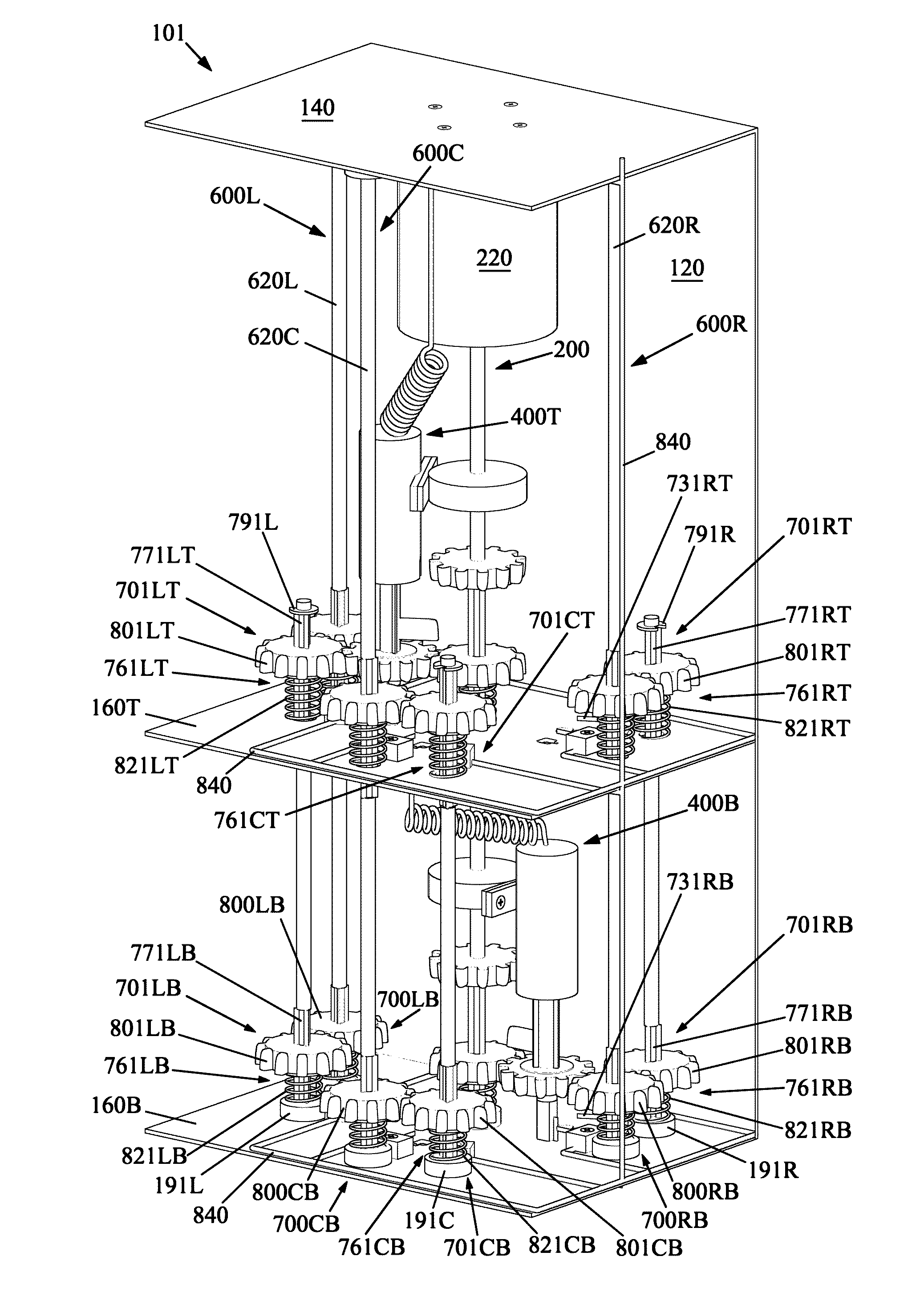
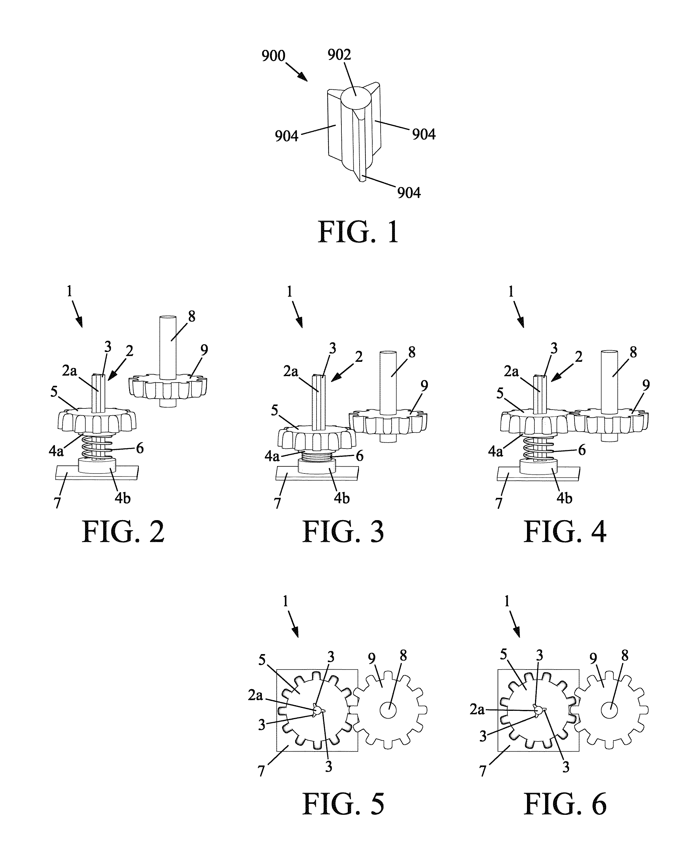
[0075]FIG. 1 depicts a three-rib section 900. Multiple instances of three-rib section 900 are used in some of the demonstrated embodiments. Three-rib section 900 comprises a rotational axis 902 comprising three ribs 904 positioned along rotational axis 902 and equidistantly located from each other around rotational axis 902.

[0076]FIGS. 2-6 depict a buffer assembly 1. Multiple instances of buffer assembly 1 are used in some of the demonstrated embodiments. Buffer assembly 1 comprises three-rib section 2 (identical to three-rib section 900) comprising a rotational axis 2a comprising three ribs 3 (best seen in FIGS. 5 and 6), a ball bearing 4a, a ball bearing 4b, a gear 5, compression spring 6, and encasing 7 (shown partially). Ball bearing 4b is mounted to encasing 7 via its outer race. Rotational axis 2a is mounted to the inner race of ball bearing 4b. Ball bearing 4a is mounted on rotational axis 2a via its inner race movable along ribs 3. Gear 5 is attached to the inner race of bal...


PUM


Abstract

A clutch by-wire capable of switching any number of clutch circuits and is capable of distributing rotary movement of a single rotary source simultaneously to any combination of the clutch circuits without stopping the rotary source, where a direction of rotary movement received by any of the clutch circuits does not depend on directions of rotary movements received by the other clutch circuits of the combination.

Description

BACKGROUND OF THE INVENTION[0001]1. Field of the Invention[0002]The present invention relates to controlled by-wire devices comprising a plurality of independent mechanical circuits, where specifically, a uniform way is desired for achieving a desired number of independent mechanical circuits regardless of an application and for engaging, at minimum, any independent mechanical circuit and, at maximum, for engaging simultaneously any combination of independent mechanical circuits regardless of a number of independent mechanical circuits, wherein each independent mechanical circuit is a mechanical circuit which is capable of receiving rotary movement regardless of other independent mechanical circuits.[0003]2. Background of the Invention[0004]The present invention is a clutch by-wire which can be used in any device requiring a plurality of independent mechanical circuits described there above, for instance, such as robotics, car power seats, etc., wherein independent mechanical circui...

Claims


Application Information

Patent Timeline
IPC IPC(8): F16D21/02F16D27/12F16D27/14
CPCF16D27/14F16H1/22Y10T74/19084Y10T74/19367
Inventor DUBE, ALISA MICHNIKMICHNIK, YEFIM
Owner DUBE ALISA MICHNIK
Why Eureka
Try Eureka