
Propulsion system

a technology of propulsion system and fluid molecule, which is applied in the direction of marine propulsion, machine/engine, vessel construction, etc., can solve the problems of affecting the safety of divers and other living systems, the inability of the propulsion system to operate further on the fluid molecule to follow up on the work, and the damage of parts in the conventional propulsion system

Active Publication Date: 2015-01-13
NICHOLSON HUGH B
View PDF11 Cites 9 Cited by
  • Summary
  • Abstract
  • Description
  • Claims
  • Application Information

AI Technical Summary

Benefits of technology

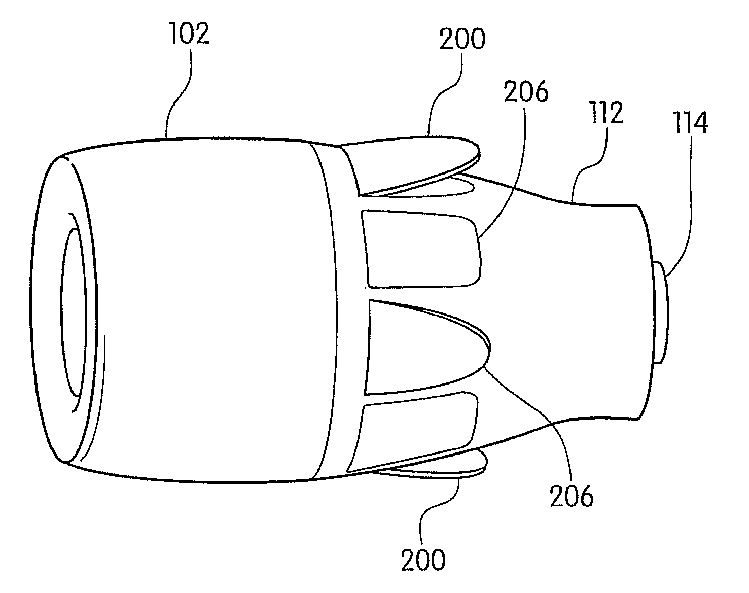
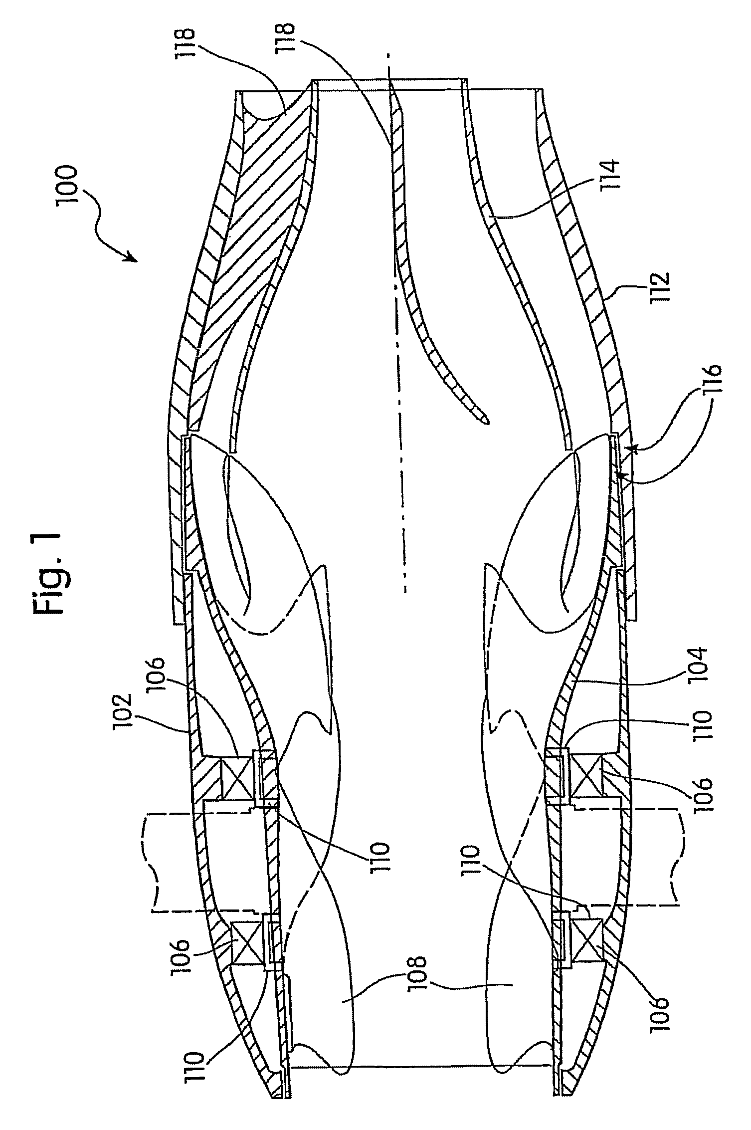
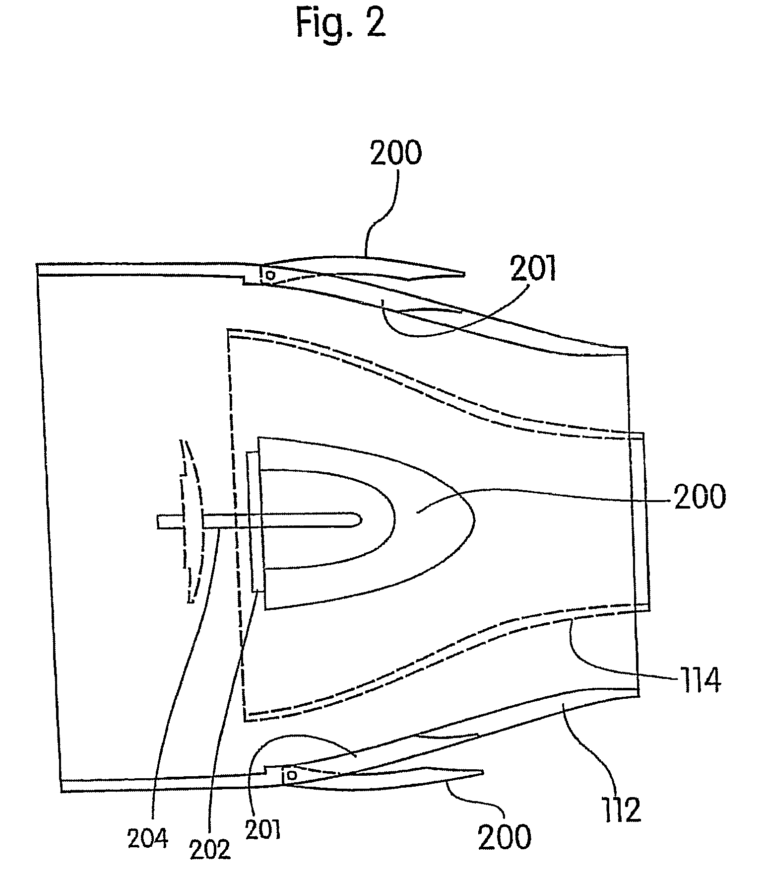
This patent describes a propulsion system that uses a cylindrical support member and a rotating tubular member to accelerate fluid flow. The system also includes a vane attached to the inside of the tubular member and a stator that engages the vane. The nozzle attached to the support member includes a primary nozzle and a secondary nozzle that work together to direct the accelerated water. The secondary nozzle has several sections that help to expand and constrict the flow, contributing to thrust. The technical effects of this system include increased efficiency and greater control over fluid flow.

Problems solved by technology

In conventional propulsion systems, propellers perform the work required to accelerate fluid molecules to a desired velocity, but the propellers are unable to operate further on the fluid molecules to follow up on the work that was expended to overcome the initial inertia.
Additionally, parts in conventional propulsion systems are easily damaged by foreign objects and unprotected screw-type propulsion systems pose a danger to divers and other living systems which pass in the vicinity of the propulsion system.

Method used


Image

  • Propulsion system
  • Propulsion system
  • Propulsion system

Examples


Embodiment Construction

[0014]Aspects of the propulsion system are disclosed in the following description and related drawings directed to specific embodiments of the propulsion system. Alternate embodiments may be devised without departing from the spirit or the scope of propulsion system. Additionally, well-known elements of exemplary embodiments of the propulsion system will not be described in detail or will be omitted so as not to obscure the relevant details of the propulsion system. Further, to facilitate an understanding of the description, discussion of several terms used herein follows.

[0015]The word “exemplary” is used herein to mean “serving as an example, instance, or illustration.” Any embodiment described herein as “exemplary” is not necessarily to be construed as preferred or advantageous over other embodiments. Likewise, the terms “embodiments of the propulsion system,” or “exemplary embodiments,” do not require that all embodiments of the propulsion system include the discussed feature, a...


PUM


Abstract

A propulsion system may include a cylindrical support member and a tubular rotatable member rotatably mounted within the support member that may be adapted to permit fluid flow therethrough. The tubular rotatable member may extend past a down stream end of the support member. An exemplary embodiment of a propulsion system may also disclose a vane attached on an interior surface of the tubular member and may include a blade which extends in a direction toward a rotational axis of the rotatable member such that rotation of the tubular member and the vane attached thereon draws fluid into the tubular member to accelerate the fluid flow through the tubular member. Additionally, a nozzle may be attached to the down stream end of the support member and include a primary nozzle and a secondary nozzle within the primary nozzle. The secondary nozzle may be engaged with the primary nozzle by a stator.

Description

CROSS REFERENCE APPLICATIONS[0001]This application is a continuation-in-part of U.S. patent application Ser. No. 12 / 071,445, filed Feb. 21, 2008, which claims priority under 35 U.S.C. 119 (e) of U.S. Provisional Application No. 60 / 996,895, filed Dec. 10, 2007, the entire contents of which are hereby incorporated by reference their entireties.BACKGROUND[0002]In conventional propulsion systems, propellers perform the work required to accelerate fluid molecules to a desired velocity, but the propellers are unable to operate further on the fluid molecules to follow up on the work that was expended to overcome the initial inertia. This is due to the fact that a fluid molecule at rest tends to remain at rest and thus once placed in motion, a relatively smaller amount of energy is required to further accelerate it. Additionally, parts in conventional propulsion systems are easily damaged by foreign objects and unprotected screw-type propulsion systems pose a danger to divers and other livi...

Claims


Application Information

Patent Timeline
Patent Type & Authority Patents(United States)
IPC IPC(8): F02K1/12B63H1/16B63H5/15B63H11/08B63H11/107B63H23/00F02K3/075
CPCB63H5/15B63H11/08B63H11/107F02K3/075B63H2001/165B63H2011/081B63H2023/005
Inventor NICHOLSON, HUGH B.
Owner NICHOLSON HUGH B
Learn More