Method device and system for indicating user equipment-specific demodulation reference signal

a reference signal and equipment technology, applied in the field of radio communication, can solve the problems of system waste, system overhead, and signaling overhead for indicating the user equipment-specific demodulation reference signal, and achieve the effect of reducing system waste and signaling overhead

Active Publication Date: 2015-01-13
CHINA MOBILE COMM GRP CO LTD
View PDF7 Cites 7 Cited by
  • Summary
  • Abstract
  • Description
  • Claims
  • Application Information

AI Technical Summary

Benefits of technology

[0012]Embodiments of the invention provide a method, device and system for indicating a user equipment-specific demodulation reference signal so as to reduce an overhead of signaling for indicating the user equipment-specific demodulation reference signal and further reduce wasted resources of a system.
[0022]In the method according to the embodiment of the invention, signal indication information is generated at the network side and the generated signal indication information is transmitted to a user equipment, and the user equipment determines information on a demodulation reference signal pattern, information on an antenna port and a scrambling identity of a reference signal sequence allocated for the user equipment according to Transport Block (TB) indication information of TBs and control information of a plurality of bits carried in the signal indication information upon reception thereof; and since TB indication information defined in the existing standard is used to indicate a demodulation reference signal pattern, an antenna port and a scrambling identity of a reference signal sequence allocated for the user equipment in the method according to the embodiment of the invention, both control signaling dedicated to indicating a user equipment-specific demodulation reference signal and an overhead of signaling for indicating a user equipment-specific demodulation reference signal is reduced and further wasted resources of a system are reduced as compared with the prior art.

Problems solved by technology

Thus if a demodulation reference signal pattern, an antenna port and a scrambling identity of a reference signal sequence allocated for a user equipment could be arbitrarily selected and combined when a user equipment-specific demodulation reference signal is indicated, then it will means a large number of allocation schemes, thus resulting in a considerable overhead of signaling for indicating the user equipment-specific demodulation reference signal and wasting resources of a system.

Method used


Image

  • Method device and system for indicating user equipment-specific demodulation reference signal
  • Method device and system for indicating user equipment-specific demodulation reference signal
  • Method device and system for indicating user equipment-specific demodulation reference signal

Examples


first embodiment

[0039]The first embodiment of the invention provides a method for indicating a user equipment-specific demodulation reference signal, which as illustrated in FIG. 6 includes:

[0040]Step S601. Signal indication information is generated at the network side, and the generated signal indication information is transmitted to a user equipment.

[0041]Step S602. The user equipment determines a demodulation reference signal pattern which is one of the Rank-2 pattern, the first Rank-4 pattern and the Rank-8 pattern, an antenna port and a scrambling identity of a reference signal sequence which is one of two scrambling identities, allocated for the user equipment according to TB indication information corresponding respectively to two TBs and 3-bit control information carried in the received signal indication information.

[0042]Particularly the Rank-2 pattern is a pattern for allocation of one or two antenna ports, the first Rank-4 pattern is a pattern for allocation of three or four antenna port...

second embodiment

[0086]The second embodiment of the invention further provides a method for indicating a user equipment-specific demodulation reference signal, which as illustrated in FIG. 7 includes:

[0087]Step S701. Signal indication information is generated at the network side, and the generated signal indication information is transmitted to a user equipment.

[0088]Step S702. The user equipment determines a demodulation reference signal pattern which is one of the Rank-2 pattern, the first Rank-4 pattern, the second Rank-4 pattern and the Rank-8 pattern, an antenna port and a scrambling identity of a reference signal sequence which is one of two scrambling identities, allocated for the user equipment according to TB indication information corresponding respectively to two TBs and 3-bit control information carried in the received signal indication information.

[0089]Particularly the Rank-2 pattern is a pattern for allocation of one or two antenna ports, the first Rank-4 pattern is a pattern for allo...

third embodiment

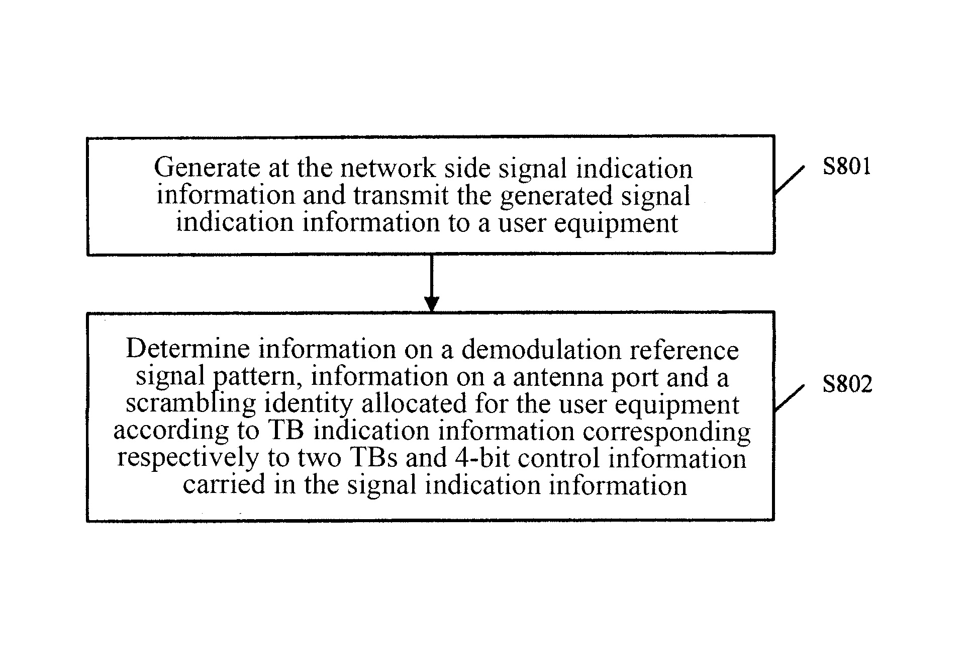
[0109]In the foregoing second embodiment, only one of the combination of the status 5 and the status 6 and the combination of the status 23 and the status 24 can be selected, and in Rank to indicate all of the status 5, the status 6, the status 23 and the status 24, the present third embodiment further provides a method for indicating a user equipment-specific demodulation reference signal, which as illustrated in FIG. 8 includes:

[0110]Step S801. Signal indication information is generated at the network side, and the generated signal indication information is transmitted to a user equipment.

[0111]Step S802. The user equipment determines a demodulation reference signal pattern which is one of the Rank-2 pattern, the first Rank-4 pattern, the second Rank-4 pattern and the Rank-8 pattern, an antenna port and a scrambling identity of a reference signal sequence which is one of two scrambling identities, allocated for the user equipment according to TB indication information correspondin...


PUM


Abstract

A method, a device and a system for indicating terminal specific Demodulation Reference Signal (DMRS) are provided by the invention. The method includes that: a network side creates signal indicating information, and sends the created signal indicating information to a terminal (S501); the terminal, according to Transmission Block (TB) indicating information of the TB and multiple bits control information which are included in the signal indicating information, confirms DMRS pattern information, antenna port information and a scrambling ID of a reference signal sequence (S502) allocated for itself. The method, the device and the system provide by the invention, compared to the prior art, reduce signaling overhead which indicates the terminal specific DMRS, thus reducing resources waste of the system.

Description

RELATED APPLICATIONS[0001]The present application is a U.S. National Stage of International Application No. PCT / CN2011 / 000188, filed 31 Jan. 2011, designating the United States, and claiming priority to Chinese Patent Application No. 201010107276.1 filed 5 Feb. 2010, the contents of which are herein incorporated by reference in their entiretyFIELD OF THE INVENTION[0002]The present invention relates to the field of radio communication and particularly to a method, device and system for indicating an MIMO (Multiple-Input Multiple-Output)-based user equipment-specific demodulation reference signal.BACKGROUND OF THE INVENTION[0003]In a Long Term Evolution-A (LTE-A) system, MIMO transmission of up to the Rank of 8 is supported, and at present the MIMO transmission scheme is implemented based upon a user equipment-specific demodulation reference signal, where indication information is transmitted together with data from the network side to a user equipment over a physical downlink control...

Claims


Application Information

Patent Timeline
Patent Type & Authority Patents(United States)
IPC IPC(8): H04B7/02H04L27/26H04B7/04H04L5/00
CPCH04L5/0023H04L5/0051
Inventor XU, XIAODONGTANG, HAIWANG, QIXINGSHI, ZHIHUALIU, JIANJUN
Owner CHINA MOBILE COMM GRP CO LTD
Why Eureka
Try Eureka