LED room light with multiple LEDs and radiator fins

a technology of led room lights and radiator fins, which is applied in the direction of semiconductor devices for light sources, lighting and heating devices, lighting support devices, etc., can solve the problems of destroying the led itself and discharging the heat from the led, and achieve the effect of huge sales potential

Inactive Publication Date: 2015-02-03
ANDERSON LEROY E
View PDF13 Cites 0 Cited by
  • Summary
  • Abstract
  • Description
  • Claims
  • Application Information

AI Technical Summary

Benefits of technology

[0005]The bulb also includes a globe of glass, plastic, or other material which covers the LED and which terminates at the upper edge of the radiator section. The globe serves to provide a grip for a user when screwing the bulb into an incandescent bulb socket. It also protects the LED bulb from contact with foreign objects. The interior of the globe does not need to be evacuated.
[0009]Emergency lights are used in schools, office buildings, apartment buildings, churches and public buildings worldwide making their potential sales huge. Emergency stairway lighting can benefit from using LEDSs to more effectively project light downward onto stairs where it is needed in an emergency situation. Many current stairway emergency lights waste their light by directing at least half of it upward toward the ceiling. An LEDS would allow all the light emitted from emergency lights to go straight downward onto the stairs. An added benefit of using LEDSs with stairway emergency lights is that, since they use energy-efficient LEDs, the battery life would last 4 to 8 hours rather than the average 1.5 hours for incandescent bulbs.

Problems solved by technology

A problem with all LED lights is dissipating the heat from the LED itself.
The heat from the LED is enough to easily destroy the LED itself unless it is conducted away from the LED so that the LED stays below the critical temperature of that particular model of LED.

Method used


Image

  • LED room light with multiple LEDs and radiator fins
  • LED room light with multiple LEDs and radiator fins

Examples


Embodiment Construction

[0014]While the presently disclosed inventive concept(s) is susceptible of various modifications and alternative constructions, certain illustrated embodiments thereof have been shown in the drawings and will be described below in detail. It should be understood, however, that there is no intention to limit the inventive concept(s) to the specific form disclosed, but, on the contrary, the presently disclosed and claimed inventive concept(s) is to cover all modifications, alternative constructions, and equivalents falling within the spirit and scope of the inventive concept(s) as defined in the claims.

[0015]Several preferred embodiments of the LED light bulb of the invention are shown in the Figures.

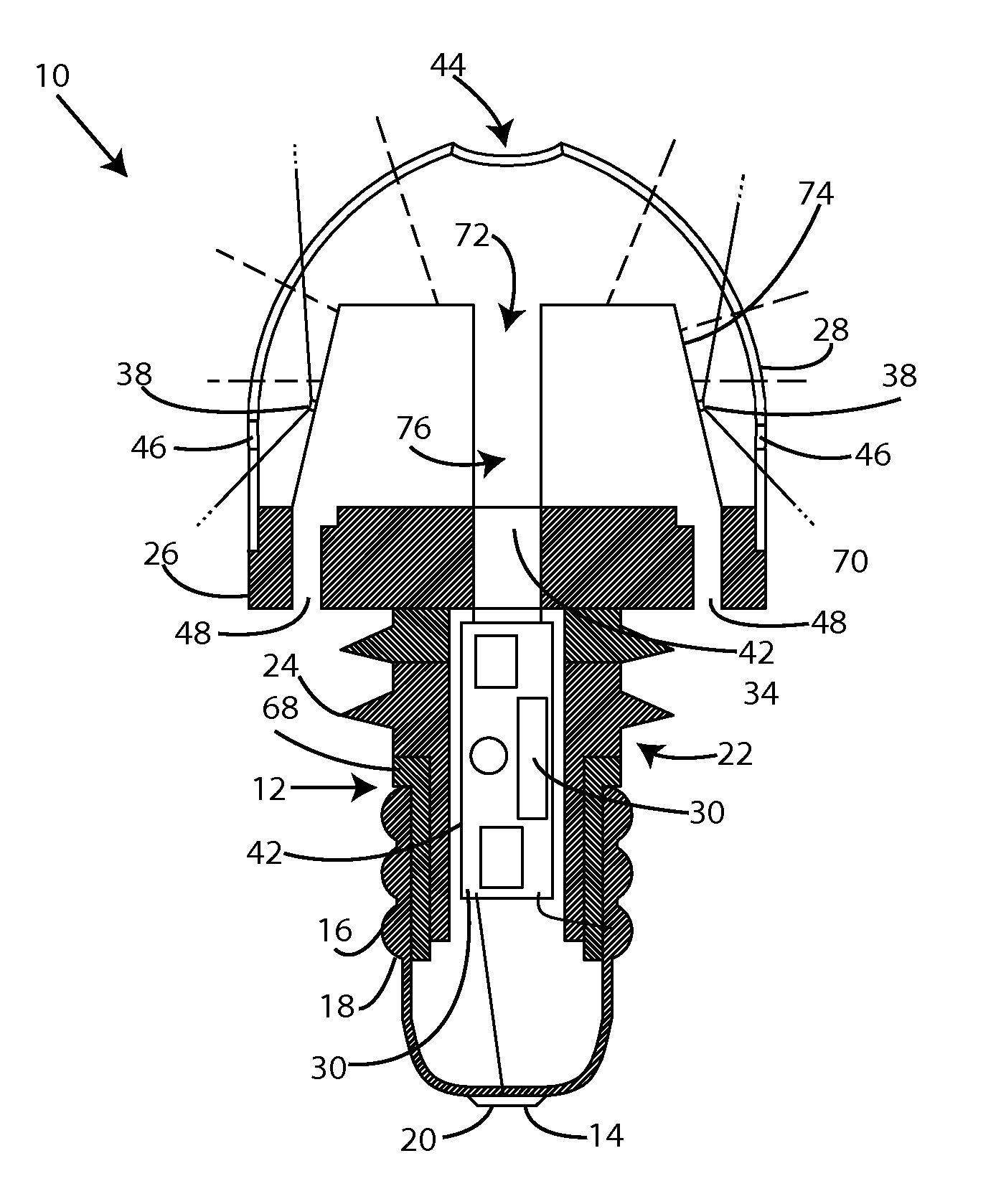
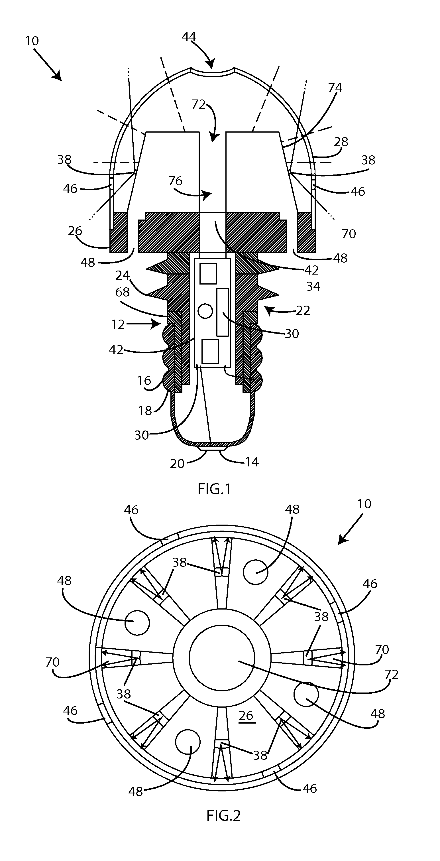
[0016]FIG. 1 shows the LED light bulb 10 of the invention. It includes a bulb base 12 to which is attached a first electrode 14 and a second electrode 16. The second electrode 16 is electrically connected to the sidewall 18 of the bulb base. The bulb base 12 fits into a standard electrica...


PUM

PropertyMeasurementUnit
angleaaaaaaaaaa
electricallyaaaaaaaaaa
structural strengthaaaaaaaaaa

Abstract

Disclosed is a light bulb which utilizes LEDs which replaces an incandescent light bulb in a fixture for incandescent light bulbs. The LED light bulb includes a multiple fins on a globe base, with an LED light on an outward facing side of each fin. The fins are in contact with heat dissipation structures, and they are adjacent to air vents which aid in heat dissipation. The heat dissipation structures include a heat transfer column which extends from the LEDs to the base of the bulb. A removable cover is enclosed which has openings for air circulation within the globe of the light bulb.

Description

BACKGROUND[0001]Light emitting diodes (LEDs) have been used in recent years in more and more lighting applications. Some have been used to light room lights, and even to operate in fixtures for conventional light bulbs. A problem with all LED lights is dissipating the heat from the LED itself. The heat from the LED is enough to easily destroy the LED itself unless it is conducted away from the LED so that the LED stays below the critical temperature of that particular model of LED. That critical temperature is typically above 200°. LED equipped light bulbs have dealt with the problem of dissipating in various ways. This can include making the output of the LEDs fairly low, having a large number of LEDs so that each one does not have to put out a lot of heat, and having various structures for dissipating heat. Improved ways of dissipating heat and making LEDs function to replace conventional incandescent light bulbs is therefore a desirable goal of a new product. The excellent ratio ...

Claims


Application Information

Patent Timeline
Patent Type & Authority Patents(United States)
IPC IPC(8): F21V29/00F21K99/00F21V3/00F21V3/02F21V3/04F21Y101/02
CPCF21V29/004F21V29/2225F21V29/2293F21K9/1355F21V3/005F21V3/02F21V29/2243F21V3/0418F21V3/0436F21Y2101/02F21V29/506F21V29/76F21V29/77F21V29/83F21K9/23F21Y2115/10F21V3/062F21V3/061F21V29/74
Inventor ANDERSON, LEROY E.
Owner ANDERSON LEROY E
Why Eureka
Try Eureka